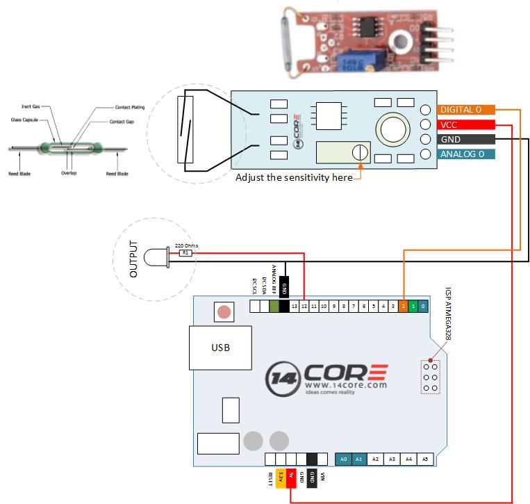
On this illustration we will going to wire the Reed Switch Module. This module provides an analog as well as digital interface, as you can see on the board it has a potentiometer / trimmer used as a pull up resistor. Reed switch module has on-board LED indicator built-in as indicator that the reed switch detected a magnet close to the switch. This is just a simple circuit to produce a switching mechanism using electromagnetism. Visit this link for more details about Reed Switch.
Required Components
- Arduino Board, AVR, STM, ESP8266
- Reed Switch Module
- Solder-less Breadboard
- Jumper Wires
Wiring Diagram for Digital
Source Code / Sketch Code for Digital
|
1 2 3 4 5 6 7 8 9 10 11 12 13 14 15 16 17 18 19 20 21 22 23 24 25 26 27 28 29 30 31 32 33 34 35 36 37 38 39 |
/* 14CORE Test Code for: Reed Switch on Digital .:+osysso++:` `+yhs/-` `-+s+` `:/+++++++++` .:/++ooo++/-` .ooooooooooo+: :///////////- `odh/` `:y+` /ddhsooooooo+ /hddhsooooydddh sdddoooooosdddy` `////////////` -hds` `sy. +ddy` .ddd: sddy.dddo +ddd- .-----------` `hds :sssss/ -ossssso-yy` `hdd: oddy `ddd/oddd:......+dddo .++++++++++++ +dd` :sdddh` :ydddddddo +y/ .ddd+........ `hddy:.....:yddy.hdddddddddddy+. ```````````` ydy .hddd/+hdddhydddh/.+yo /hdddddddddd. :shddddddddhs/`+ddd:````-yddy- :ooooooooooo+ odh` sdddooyyyyyhddddyy.sy+ ` `......... ``.... ....` ```...` ` `` `` ` -dd+`::::` .:::- /yy. -oos+:-oos+--oos+: /o `+y o/: o:+/ h:`yos /+-`/+/+ s:y/y. /dd/ `+yy: +//+ +/:+ +/:+ -. `/ -:o.:/:`//+- + +:- :`-+:`://: +`o`+. -yds. `/yys- .`-.. .``` ```` .`` ` ` ``` ``-..` ` :ydy/.`````.-/oyhs: `+++oo+oo+:.+-++/-/ooo+o +:o/oo///:+/ .:oyhhhhhhhso:` `. ``` */ int MyLedOutput = 12 ; // Define as Output Interface (Optional) int MySensor = 2; // Define as the REED sensor digital pin 2 on microcontroller int Value ; // Define as numeric value to hold the sensor input void setup () { pinMode (MyLedOutput, OUTPUT) ; // Define as digital output (LED which is connected to pin 12) pinMode (MySensor, INPUT) ; // Define as digital input } void loop () SunFounder{ Value = digitalRead (MySensor) ; // Reads the state value of digital input in pin 2 if (Value == HIGH) // If sensor reads pin 2 is HIGH then turn the LED pin 12 ON { digitalWrite (MyLedOutput, HIGH); } else { digitalWrite (MyLedOutput, LOW); // Otherwise turn off or LOW } } |
Wiring Diagram for Analog

Source Code / Sketch Code for Analog
|
1 2 3 4 5 6 7 8 9 10 11 12 13 14 15 16 17 18 19 20 21 22 23 24 25 26 27 28 29 30 31 32 33 34 35 |
/* 14CORE Test Code for: Reed Switch on Analog .:+osysso++:` `+yhs/-` `-+s+` `:/+++++++++` .:/++ooo++/-` .ooooooooooo+: :///////////- `odh/` `:y+` /ddhsooooooo+ /hddhsooooydddh sdddoooooosdddy` `////////////` -hds` `sy. +ddy` .ddd: sddy.dddo +ddd- .-----------` `hds :sssss/ -ossssso-yy` `hdd: oddy `ddd/oddd:......+dddo .++++++++++++ +dd` :sdddh` :ydddddddo +y/ .ddd+........ `hddy:.....:yddy.hdddddddddddy+. ```````````` ydy .hddd/+hdddhydddh/.+yo /hdddddddddd. :shddddddddhs/`+ddd:````-yddy- :ooooooooooo+ odh` sdddooyyyyyhddddyy.sy+ ` `......... ``.... ....` ```...` ` `` `` ` -dd+`::::` .:::- /yy. -oos+:-oos+--oos+: /o `+y o/: o:+/ h:`yos /+-`/+/+ s:y/y. /dd/ `+yy: +//+ +/:+ +/:+ -. `/ -:o.:/:`//+- + +:- :`-+:`://: +`o`+. -yds. `/yys- .`-.. .``` ```` .`` ` ` ``` ``-..` ` :ydy/.`````.-/oyhs: `+++oo+oo+:.+-++/-/ooo+o +:o/oo///:+/ .:oyhhhhhhhso:` `. ``` */ int AnalogSensorPin = A0; // Define as Analog Input Signal from the Sensor int LedOutIndicator = 12; // Define as Output indicator (Optional) int Value = 0; // variable to store the value from the sensor void setup () { pinMode (LedOutIndicator, OUTPUT); Serial.begin (9600); // Start Serial Communication } void loop () { Value = analogRead (AnalogSensorPin); digitalWrite (LedOutIndicator, HIGH); delay (Value); digitalWrite (LedOutIndicator, LOW); delay (Value); Serial.print("SENSOR PIN A0:") Serial.println (Value, DEC); } |
Wiring Reed Switch Module with Arduino Microcontroller


