Gears are like wheels with teeth mesh together and make things turn. Gear are used to transfer motion or power from one moving part to another. A gear is rotating machine part have cut teeth, or cogs, along with another toothed to transmit torque,
Purse of the gears generally used to reverse the direction of rotation, increase or decrease the speed of rotary motion, to move rotating motion to a different axis, to keep the rotation of 2 axis synchronized.
Spur Gears are same gears to move opposite of each other because they are meshed together. Gear (A) is a driver turned by the motor meshes with gear (B) are called driven gear.
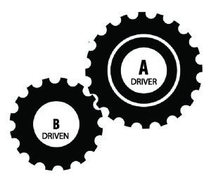
The Spur Gear
The pitch circle of a gear is very important, it is used by engineers to determine the shape of the teeth and the ratio between gear. The pitch of a gear is the distance between any point on 1 tooth and same point of the next tooth and the root is the bottom part of a gear.

Worm Wheel Gear System
Below some of the example of gears named worm and worm wheel gear, this gear which in this example below it has one tooth but it is like a screw thread, like a normal gear wheel or spur gear this worm gear always drives the worm wheel round, it is not the opposite way round.

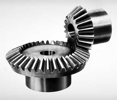
Bevel Gear System
Bevel Gears is used to change the direction of drive gear by 90 Degrees, bevel gears change the rotation of chuck to a horizontal rotation.
Rack & Pinion Gear System
The Rack & Pinion Gear System is compose of two gears. The pinion is a normal spur gear and the rack is a straight or flat gear and they mesh with the teeth of the pinion gear and the pinion rotates and move the rack in a straight line.

Compound Gear System
Compound Gear are used mostly in Automobile Engines, Workshop Machinery, Robotics and man other mechanical devices. Sometime the compound gears are used mostly so that the final gear in a gear train rotates at the exact speed.

The Gear Ratio / Velocity Ratio
Gears are change due to what is called Gear Ratio / Velocity Ratio. Gear ratio can worked in the form of numbers, basically the ratio is determined by the number of teeth on each gear. ( Every 3 rotations of the driving gear, the driven gear will rotate 1. )

The Gear Ratio into 3 Gear System with rev/min

Reading the RPM (Revolutions Per Minute)
Driver gear is the larger than the Driven gear, the rule is large to mall gear means (x) multiply the velocity ratio, the RPM of the first gear (/) divided by 60 teeth by 30 teeth to the velocity ratio of 1:2 then multiply this number 2 by 120 RPM it will give you the answer of 240rpm.


Sir,
Very informative
I am working on an astronomical clock based on Indian time concept
I need a drive with 0.4 rpm !!!
I got a motor with 3 rpm , suggest gear for such reduction from 3 to 0.4
I amy need yr guidance as I proceed with my project
Maybe I can buy some wooden gears if you have
Yr aricle is educative too
God bless
Bala