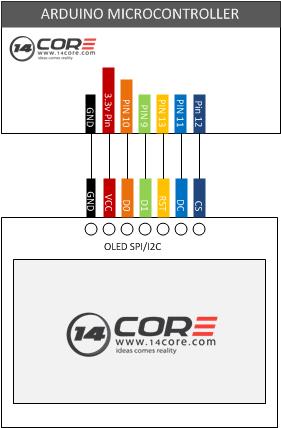
In this illustration we will going to wire the 128×64 OLED display screen, using SPI and I2C. As you can see the diagram below we used the Pin 5 to Pin 8 in Arduino Microcontroller to wire our OLED Display screen.
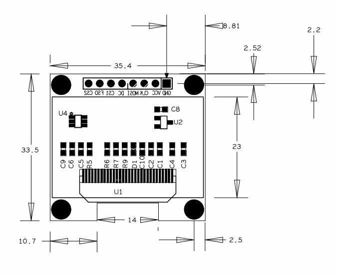
This display module has only 0.96” diagonal made of 128×64 OLED pixels, this module it works without backlight can be visible in the dark environment, OLED display is higher compared to LCD display. This OLED Display driven by SSD1306 chip compatible with i2C or SPI Bus communication, as you can see there are 2 resistors at the back of the module and sick-screen to see how to set the communication mode, the default mode is 4wire SPI mode except VCC and GND, 4wires would be need when using 4wires SPI mode. You can also set to the I2C mode, in which mode 2 control wires is needed.
Two types of version for this device

i2C
- GND
- VCC
- SCL
- SDA
SPI
6 Pins!, note SCL=CLK, SDA=MOSI, not IIC pins
- GND
- VCC
- CLK (SCL)
- MOSI(SDA)
- CS (chip select)
- D/C
Required Components
1x Arduino UNO/MEGA/LEO/NANO/PRO
1x 128×64 OLED Display Screen Module
1x Solder Less Bread Board
1x Jumper Wires
Wiring Diagram
Arduino Sketch
|
1 2 3 4 5 6 7 8 9 10 11 12 13 14 15 16 17 18 19 20 21 22 23 24 25 26 27 28 29 30 31 32 33 34 35 36 37 38 39 40 41 42 43 44 45 46 47 48 49 50 51 52 53 54 55 56 57 58 59 60 61 62 63 64 65 66 67 68 69 70 71 72 73 74 75 76 77 78 79 80 81 82 83 84 85 86 87 88 89 90 91 92 93 94 95 96 97 98 99 100 101 102 103 104 105 106 107 108 109 110 111 112 113 114 115 116 117 118 119 120 121 122 123 124 125 126 127 128 129 130 131 132 133 134 135 136 137 138 139 140 141 142 143 144 145 146 147 148 149 150 151 152 153 154 155 156 157 158 159 160 161 162 163 164 165 166 167 168 169 170 171 172 173 174 175 176 177 178 179 180 181 182 183 184 185 186 187 188 189 190 191 192 193 194 195 196 197 198 199 200 201 202 203 204 205 206 207 |
#define OLED_DC 11 // DC define at Arduino Pin 11 #define OLED_CS 12 // CD define at Arduino Pin 12 #define OLED_CLK 10 // CLK define at Arduino Pin 10 #define OLED_MOSI 9 // MOSI define at Arduino Pin 9 #define OLED_RESET 13 // RST define at Arduino Pin 13 #include <SSD1306.h> // SSD1306 Code Library SSD1306 oled(OLED_MOSI, OLED_CLK, OLED_DC, OLED_RESET, OLED_CS); #define NUMFLAKES 10 #define XPOS 0 #define YPOS 1 #define DELTAY 2 #define LOGO16_GLCD_HEIGHT 16 #define LOGO16_GLCD_WIDTH 16 static unsigned char __attribute__ ((progmem)) logo16_glcd_bmp[]={ 0x30, 0xf0, 0xf0, 0xf0, 0xf0, 0x30, 0xf8, 0xbe, 0x9f, 0xff, 0xf8, 0xc0, 0xc0, 0xc0, 0x80, 0x00, 0x20, 0x3c, 0x3f, 0x3f, 0x1f, 0x19, 0x1f, 0x7b, 0xfb, 0xfe, 0xfe, 0x07, 0x07, 0x07, 0x03, 0x00, }; void setup() { Serial.begin(9600); // If you want to provide external 7-9V VCC, uncomment next line and comment the one after //oled.ssd1306_init(SSD1306_EXTERNALVCC); // by default, we'll generate the high voltage from the 3.3v line internally! (neat!) oled.ssd1306_init(SSD1306_SWITCHCAPVCC); // init done oled.display(); // show splashscreen delay(2000); oled.clear(); // clears the screen and buffer // Fill Oled screen oled.fillrect(0, 0, SSD1306_LCDWIDTH-1, SSD1306_LCDHEIGHT-1, WHITE); oled.display(); delay(2000); // Set to draw a single pixel oled.setpixel(10, 10, WHITE); oled.display(); delay(2000); oled.clear(); // Set to draw many lines testdrawline(); oled.display(); delay(2000); oled.clear(); //Set to draw rectangles testdrawrect(); oled.display(); delay(2000); oled.clear(); //Set to draw multiple rectangles testfillrect(); oled.display(); delay(2000); oled.clear(); //Set to draw mulitple circles testdrawcircle(); oled.display(); delay(2000); oled.clear(); //Set to draw a white circle, 10 pixel radius, at location (32,32) oled.fillcircle(32, 32, 10, WHITE); oled.display(); delay(2000); oled.clear(); //Set to draw the first ~12 characters in the font testdrawchar(); oled.display(); delay(2000); oled.clear(); //Set to draw a string at location (0,0) oled.drawstring(0, 0, "Lorem ipsum dolor sit amet, consectetur adipisicing elit, sed do eiusmod tempor incididunt ut labore et dolore magna aliqua. Ut enim ad minim veniam, quis nostrud exercitation"); oled.display(); delay(2000); oled.clear(); //Set to miniature bitmap display oled.drawbitmap(30, 16, logo16_glcd_bmp, 16, 16, 1); oled.display(); //Set to invert the display oled.ssd1306_command(SSD1306_INVERTDISPLAY); delay(1000); oled.ssd1306_command(SSD1306_NORMALDISPLAY); delay(1000); //Set to draw a bitmap icon and 'animate' movement testdrawbitmap(logo16_glcd_bmp, LOGO16_GLCD_HEIGHT, LOGO16_GLCD_WIDTH); } // loop all the function above void loop() { for (uint8_t i=0; i<SSD1306_LCDWIDTH; i++) { for (uint8_t j=0; j<SSD1306_LCDHEIGHT; j++) { oled.setpixel(i, j, WHITE); oled.display(); } } } void testdrawbitmap(const uint8_t *bitmap, uint8_t w, uint8_t h) { uint8_t icons[NUMFLAKES][3]; srandom(666); // whatever seed // initialize the display for (uint8_t f=0; f< NUMFLAKES; f++) { icons[f][XPOS] = random() % SSD1306_LCDWIDTH; icons[f][YPOS] = 0; icons[f][DELTAY] = random() % 5 + 1; Serial.print("x: "); Serial.print(icons[f][XPOS], DEC); Serial.print(" y: "); Serial.print(icons[f][YPOS], DEC); Serial.print(" dy: "); Serial.println(icons[f][DELTAY], DEC); } while (1) { //Set to draw each icon for (uint8_t f=0; f< NUMFLAKES; f++) { oled.drawbitmap(icons[f][XPOS], icons[f][YPOS], logo16_glcd_bmp, w, h, WHITE); } oled.display(); delay(200); // then erase it + move it for (uint8_t f=0; f< NUMFLAKES; f++) { oled.drawbitmap(icons[f][XPOS], icons[f][YPOS], logo16_glcd_bmp, w, h, BLACK); // move it icons[f][YPOS] += icons[f][DELTAY]; // if its gone, reinit if (icons[f][YPOS] > SSD1306_LCDHEIGHT) { icons[f][XPOS] = random() % SSD1306_LCDWIDTH; icons[f][YPOS] = 0; icons[f][DELTAY] = random() % 5 + 1; } } } } void testdrawchar(void) { for (uint8_t i=0; i < 168; i++) { oled.drawchar((i % 21) * 6, i/21, i); } } void testdrawcircle(void) { for (uint8_t i=0; i<SSD1306_LCDHEIGHT; i+=2) { oled.drawcircle(63, 31, i, WHITE); } } void testdrawrect(void) { for (uint8_t i=0; i<SSD1306_LCDHEIGHT; i+=2) { oled.drawrect(i, i, SSD1306_LCDWIDTH-i, SSD1306_LCDHEIGHT-i, WHITE); } } void testfillrect(void) { for (uint8_t i=0; i<SSD1306_LCDHEIGHT; i++) { // alternate colors for moire effect oled.fillrect(i, i, SSD1306_LCDWIDTH-i, SSD1306_LCDHEIGHT-i, i%2); } } void testdrawline() { for (uint8_t i=0; i<SSD1306_LCDWIDTH; i+=4) { oled.drawline(0, 0, i, SSD1306_LCDHEIGHT-1, WHITE); oled.display(); } for (uint8_t i=0; i<SSD1306_LCDHEIGHT; i+=4) { oled.drawline(0, 0, SSD1306_LCDWIDTH-1, i, WHITE); oled.display(); } delay(1000); for (uint8_t i=0; i<SSD1306_LCDWIDTH; i+=4) { oled.drawline(i, SSD1306_LCDHEIGHT-1, 0, 0, BLACK); oled.display(); } for (uint8_t i=0; i<SSD1306_LCDHEIGHT; i+=4) { oled.drawline(SSD1306_LCDWIDTH - 1, i, 0, 0, BLACK); oled.display(); } } |
Download the download code library here | Zip
Download the SSD1780 Datasheet here | Pdf
Download the Image to byte array Generator | Download Area


