The L298 Dubai H Bridge is base on l298 Chip manufacture by ST Semiconductor. The l298 is an integrated monolithic circuit in a 15 lead multi-watt and power S020 package. It is a high voltage and high current full dual bridge driver designed to accept standard TTL logic level and drive inductive loads such as relays, solenoids and DC stepper motor.
Two enabled inputs are provided to enable or disable the device independently of the input signals. The emitters of the lower transistors of each bridge are connected together and the corresponding external terminal can be use for the connection of external sensing resistor. Additional supply input is provided so that the logic works at lower voltage.
This module has ease to connect and drive a dc motor or stepper motor allows you to easily and intently control two motor up to 2A each in both direction or one stepper motor.
It is excellent for robotics applications and well fit to a microcontroller. It can also be interfaced with simple manual switches, TTL Logic gates and relays. etc
Specification
- Motor supply: 7 to 24 VDC
- Control Logic: Standard TTL Logic Level
- Output Power: Up to 2 A each
- Enable and Direction Control Pins
- Heat Sink
- Power-On LED indicator
- 4 Direction LED indicators
There are many model of l298n boards in the market, see the photo below for examples. All of this devices are same functions and features.

The L298n Schematic Diagram

How to control a Stepper Motor with L298n Modules.
What is a stepper motor?
A digital electric motor that moves one step at a time and each step is defined by a step angle. The stepper motor moves is distinct steps during its rotation. Each steps is defined by a step angle. In the example below you may notice that there are 4 distinct steps for the rotor to make a complete 360 degree rotation. As defines in step angle at 90 degrees. Since the stepper motor does move in discreet movement, we can say that a stepper motor is actually a digital motor. This characteristic makes it very suitable for digital interfaces integrates with a microcontroller. if you want to learn more about Stepper Motor download the reference below.

In this example we will going to use the 14HM Series 2 Phase Hybrid Stepper Motor

Wiring diagram
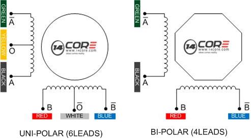
The stepper motor has 200 steps per revolution and can operate at 60RPM. See the wiring diagram below. Connect the A+,A-, B+ and B- wires from the stepper motor to the module connection OUT 1, OUT 2, OUT3, and OUT4 or A1, A2, B3, and B4. Place the jumper included with the L298n Module over the pin. As you can see the diagram below, Red, Green, Yellow, and Blue are connected into the l298n board pin.
Hardware Details
| Screw terminal pin assignments | |||
| Pin | Color | Name | Description |
| 1 | Green | Motor A – | Output to Motor A (-) |
| 2 | Green | Motor A+ | Output to Motor A (+) |
| 3 | Blue | VMS | Input 4-35V motor power supply (+) |
| 4 | Blue | GND | Ground (-) |
| 5 | Blue | 5V | 5V regulated power (+) |
| 6 | Green | Motor B – | Output to Motor B (-) |
| 7 | Green | Motor B+ | Output to Motor B (+) |
Note that the 5V regulated power on pin 5 above is an output when the 5V_EN jumper is in place. Otherwise you must input 5V regulated power at pin 5 so that the circuit can operate properly. Do not enable the onboard 5V regulator if you are supplying more than 16V to motors on pin 3 or the regulator will burn out.
| Header pin assignments | ||
| Pin | Name | Description |
| 1 | ENA | Input to enable Motor A |
| 2 | IN1 | Input to control Motor A |
| 3 | IN1 | Input to control Motor A |
| 4 | ENA | Input to enable Motor B |
| 5 | IN1 | Input to control Motor B |
| 6 | IN2 | Input to control Motor B |
| Jumpers | |
| Name | Description |
| 5V_EN | Enable the onboard 5V regulator |
| U1 | Enable Motor A input pin IN2 pull-up resistor (10K) |
| U2 | Enable Motor A input pin IN2 pull-up resistor (10K) |
| U3 | Enable Motor B input pin IN3 pull-up resistor (10K) |
| U4 | Enable Motor B input pin IN4 pull-up resistor (10K) |
| CSA | Ties the Motor A current sense to ground |
| CSB | Ties the Motor B current sense to ground |
Note: The CSA and CSB current sense feature is disabled when the jumpers are present. To use the current sense feature, remove the jumpers and attach to the header pins. Leave the jumper connected when not using current sense.
Software
Speed control
The speed of the motors can be adjusted by connecting PWM outputs from your robot’s microcontroller to the ENA and ENB input pins on the motor driver board. The ENA pin controls Motor A and the ENB pin controls Motor B. When these pins are HIGH, power is output to the motor. By using PWM, you are turning power on and off very quickly to adjust the speed of the motor. The longer the PWM duty cycle is, the faster the motor will turn. We recommend always using a PWM duty cycle of 90% or less.
Direction control
The direction that the motors turn is controlled using the IN1, IN2, IN3 and IN4 input pins on the motor driver board. Connect these pins to digital outputs on your robots microcontroller. To make Motor A go forward, set IN1=HIGH and IN2=LOW. To make Motor A go backward set IN1=LOW and IN2=HIGH. The same method is used to control Motor B: set IN3=HIGH and IN4=LOW to o forward and set IN3=LOW and IN4=HIGH to go backwards. Note that “forward” and “backwards” refer to the direction of the motors themselves. If your robot does not move in the expected direction, reverse the motor polarity by swapping the green screw terminals for Motor A + and – and/or Motor B + and -.
Stopping
To remove power from the motors, simply set ENA=LOW for Motor A and ENB=LOW for Motor B. This will result in the motors stopping slowly and naturally from friction. To perform a quick braking operation, set ENA=LOW, IN1=LOW and IN2=LOW for Motor A and ENB=LOW, IN3=LOW and IN4=LOW for Motor B. The motors will come to an instant stop. Here are some handy tables to show the various modes of operation.
Motor Driver Truth Tables
Here are some handy tables to show the various modes of operation.
| Motor A truth table | |||
| ENA | IN1 | IN2 | Description |
| 0 | N/A | N/A | Motor A is off |
| 1 | 0 | 0 | Motor A is stopped (brakes) |
| 1 | 0 | 1 | Motor A is on and turning backwards |
| 1 | 1 | 0 | Motor A is on and turning forwards |
| 1 | 1 | 1 | Motor A is stopped (brakes) |
| Motor B truth table | |||
| ENB | IN3 | IN4 | Description |
| 0 | N/A | N/A | Motor B is off |
| 1 | 0 | 0 | Motor B is stopped (brakes) |
| 1 | 0 | 1 | Motor B is on and turning backwards |
| 1 | 1 | 0 | Motor B is on and turning forwards |
| 1 | 1 | 1 | Motor B is stopped (brakes) |
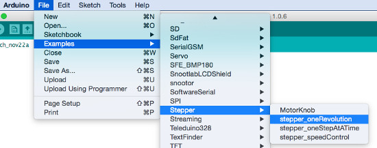
Connecting the 4 wire Stepper Motor to Arduino

Controlling the stepper motor from Arduino IDE is very simple, because Arduino IDE has already included a Library to control a stepper motor. Just simply load the stepper_oneRevolution sketch has already included stepper library.
Open you your Arduino IDE just follow the instruction below.
Download the introduction to Stepper Motors | PDF
Download the 14HM Series Datasheet | PDF
Download the L298n Datasheet | PDF


A helpful article but…..Your ppt on intro to stepper motors refers to Flemings Right Hand Rule. The Left Hand rule is used for motors.