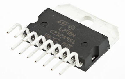
 The L298 H Bridge is base on l298 Chip manufacture by ST Semiconductor. The l298 is an integrated monolithic circuit in a 15 lead multi-watt and power S020 package. It is a high voltage and high current full dual bridge driver designed to accept standard TTL logic level and drive inductive loads such as relays, solenoids and DC stepper motor.
Two enabled inputs are provided to enable or disable the device independently of the input signals. The emitters of the lower transistors of each bridge are connected together and the corresponding external terminal can be use for the connection of external sensing resistor. Additional supply input is provided so that the logic works at lower voltage.
This module has ease to connect and drive a dc motor or stepper motor allows you to easily and intently control two motor up to 2A each in both direction or one stepper motor.
It is excellent for robotics applications and well fit to a microcontroller. It can also be interfaced with simple manual switches, TTL Logic gates and relays. etc
Specification
- Motor supply: 7 to 24 VDC
- Control Logic: Standard TTL Logic Level
- Output Power: Up to 2 A each
- Enable and Direction Control Pins
- Heat-Sink
- Power-On LED indicator
- 4 Direction LED indicators
There are many model of l298n boards in the market, see the photo below for examples. If you want to build your own, see the schematic diagram below.

L298n Schematic Diagram

How to control 1, 2, or 4 DC Motors
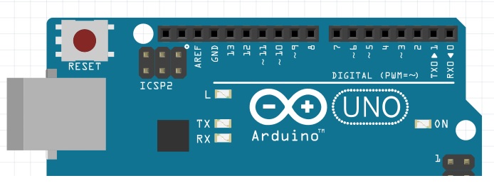
Wiring and controlling a DC motor is quite easy, you just need to connect each motor to A1-A2, B3-B4 or Out 1-2, Out 3-4 It depends how the L298n board configuration. If your using two motors for a robot you need to ensure that the polarity of the motors is the same on both outputs, otherwise you need to swap them when you set the motors to forward and backward. We need to connect 6 digital output pins on your Arduino. 2 of the pins you need to used PWM(Pulse with Modulation) pins. PWM pins are denoted by symbol (~) next to the pin Number.
 .
.
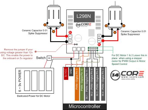
Connect the Arduino Digital Pins to the L298n Module see our example diagram below, in the diagram we have 4 and 2 DC motors so digital pins D9 D8, D7 and D6 will be connected to IN1, IN2, IN3, and IN4. Then connect Digital 10 to module pin PWM 1 you need to remove the jumper fist plug Digital 5 to module PWM 2. The motor direction is controlled by sending a HIGH or LOW signal to the driver on each channel.
for example Motor A1 and A2 a HIGH to IN1 and LOW to IN2 will cause it to turn in one direction and LOW and HIGH will cause it to turn in other direction. Controlling the Speed of the motor you need to used the PWM(Pulse with Modulation) signal from the digital pin connected to the Arduino enabled pin can. Below are the sample sketch to test and drive the motors with PWM (Pulse with Modulation).
Hardware Details
| Screw terminal pin assignments | |||
| Pin | Color | Name | Description |
| 1 | Green | Motor A – | Output to Motor A (-) |
| 2 | Green | Motor A+ | Output to Motor A (+) |
| 3 | Blue | VMS | Input 4-35V motor power supply (+) |
| 4 | Blue | GND | Ground (-) |
| 5 | Blue | 5V | 5V regulated power (+) |
| 6 | Green | Motor B – | Output to Motor B (-) |
| 7 | Green | Motor B+ | Output to Motor B (+) |
Note that the 5V regulated power on pin 5 above is an output when the 5V_EN jumper is in place. Otherwise you must input 5V regulated power at pin 5 so that the circuit can operate properly. Do not enable the onboard 5V regulator if you are supplying more than 16V to motors on pin 3 or the regulator will burn out.
| Header pin assignments | ||
| Pin | Name | Description |
| 1 | ENA | Input to enable Motor A |
| 2 | IN1 | Input to control Motor A |
| 3 | IN1 | Input to control Motor A |
| 4 | ENA | Input to enable Motor B |
| 5 | IN1 | Input to control Motor B |
| 6 | IN2 | Input to control Motor B |
| Jumpers | |
| Name | Description |
| 5V_EN | Enable the onboard 5V regulator |
| U1 | Enable Motor A input pin IN2 pull-up resistor (10K) |
| U2 | Enable Motor A input pin IN2 pull-up resistor (10K) |
| U3 | Enable Motor B input pin IN3 pull-up resistor (10K) |
| U4 | Enable Motor B input pin IN4 pull-up resistor (10K) |
| CSA | Ties the Motor A current sense to ground |
| CSB | Ties the Motor B current sense to ground |
Note: The CSA and CSB current sense feature is disabled when the jumpers are present. To use the current sense feature, remove the jumpers and attach to the header pins. Leave the jumper connected when not using current sense.
Software
Speed control
The speed of the motors can be adjusted by connecting PWM outputs from your robot’s microcontroller to the ENA and ENB input pins on the motor driver board. The ENA pin controls Motor A and the ENB pin controls Motor B. When these pins are HIGH, power is output to the motor. By using PWM, you are turning power on and off very quickly to adjust the speed of the motor. The longer the PWM duty cycle is, the faster the motor will turn. We recommend always using a PWM duty cycle of 90% or less.
Direction control
The direction that the motors turn is controlled using the IN1, IN2, IN3 and IN4 input pins on the motor driver board. Connect these pins to digital outputs on your robots microcontroller. To make Motor A go forward, set IN1=HIGH and IN2=LOW. To make Motor A go backward set IN1=LOW and IN2=HIGH. The same method is used to control Motor B: set IN3=HIGH and IN4=LOW to o forward and set IN3=LOW and IN4=HIGH to go backwards. Note that “forward” and “backwards” refer to the direction of the motors themselves. If your robot does not move in the expected direction, reverse the motor polarity by swapping the green screw terminals for Motor A + and – and/or Motor B + and -.
Stopping
To remove power from the motors, simply set ENA=LOW for Motor A and ENB=LOW for Motor B. This will result in the motors stopping slowly and naturally from friction. To perform a quick braking operation, set ENA=LOW, IN1=LOW and IN2=LOW for Motor A and ENB=LOW, IN3=LOW and IN4=LOW for Motor B. The motors will come to an instant stop. Here are some handy tables to show the various modes of operation.
Motor Driver Truth Tables
Here are some handy tables to show the various modes of operation.
| Motor A truth table | |||
| ENA | IN1 | IN2 | Description |
| 0 | N/A | N/A | Motor A is off |
| 1 | 0 | 0 | Motor A is stopped (brakes) |
| 1 | 0 | 1 | Motor A is on and turning backwards |
| 1 | 1 | 0 | Motor A is on and turning forwards |
| 1 | 1 | 1 | Motor A is stopped (brakes) |
| Motor B truth table | |||
| ENB | IN3 | IN4 | Description |
| 0 | N/A | N/A | Motor B is off |
| 1 | 0 | 0 | Motor B is stopped (brakes) |
| 1 | 0 | 1 | Motor B is on and turning backwards |
| 1 | 1 | 0 | Motor B is on and turning forwards |
| 1 | 1 | 1 | Motor B is stopped (brakes) |
Diagram for Connecting 4 Motor on L298n with Arduino

Diagram for Connecting 2 Motor on L298n with Arduino
Motor Simulation Sketch Code
|
1 2 3 4 5 6 7 8 9 10 11 12 13 14 15 16 17 18 19 20 21 22 23 24 25 26 27 28 29 30 31 32 33 34 35 36 37 38 39 40 41 42 43 44 45 46 47 48 49 50 51 52 53 54 55 56 57 58 59 60 61 62 63 64 65 66 67 68 69 70 71 72 73 74 75 76 77 78 79 80 81 82 83 84 85 86 |
/* L298N H-Bridge driving DC motor on Arduino */ int ENA = 10; // MCU PWM Pin 10 to ENA on L298n Board int IN1 = 9; // MCU Digital Pin 9 to IN1 on L298n Board int IN2 = 8; // MCU Digital Pin 8 to IN2 on L298n Board int ENB = 5; // MCU PWM Pin 5 to ENB on L298n Board int IN3 = 7; // MCU Digital pin 7 to IN3 on L298n Board int IN4 = 6; // MCU Digital pin 6 to IN4 on L298n Board void setup() { pinMode(ENA, OUTPUT); //Set all the L298n Pin to output pinMode(ENB, OUTPUT); pinMode(IN1, OUTPUT); pinMode(IN2, OUTPUT); pinMode(IN3, OUTPUT); pinMode(IN4, OUTPUT); } void DRIVEONE() { // Run the motors on both direction at fixed speed digitalWrite(IN1, HIGH); // Turn HIGH motor A digitalWrite(IN2, LOW); analogWrite(ENA, 200); // TO set the turning speed to 200 out of possible range 0 to 255 digitalWrite(IN3, HIGH); // turn HIGH motor B digitalWrite(IN4, LOW); // To set the turning speed to 200 out of possible range 0 to 255 analogWrite(ENB, 200); delay(2000); // Delay to 2 seconds // Changing the direction of the motor digitalWrite(IN1, LOW); digitalWrite(IN2, HIGH); digitalWrite(IN3, LOW); digitalWrite(IN4, HIGH); delay(2000); // Delay to 2 seconds digitalWrite(IN1, LOW); // Turn the motor off digitalWrite(IN2, LOW); // Turn the motor off digitalWrite(IN3, LOW); // Turn the motor off digitalWrite(IN4, LOW); // Turn the motor off } void DRIVETWO() { /* These function will turn the motors on the possible speeds, the maximum speed turns is determined by the motor specs and the operating voltage. The PWM(Pulse with modulation values will sent by analogWrite() function to drive the maxim speed. */ digitalWrite(IN1, LOW); digitalWrite(IN2, HIGH); digitalWrite(IN3, LOW); digitalWrite(IN4, HIGH); for (int x = 0; x < 256; x++) // Motor will accelerate from 0 to maximum speed { analogWrite(ENA, x); analogWrite(ENB, x); delay(20); } for (int y = 255; y >= 0; --y) // Motor will decelerate from maximum speed to 0 { analogWrite(ENA, y); analogWrite(ENB, y); delay(20); } digitalWrite(IN1, LOW); // Tun Off All the Motors digitalWrite(IN2, LOW); digitalWrite(IN3, LOW); digitalWrite(IN4, LOW); } void loop() { DRIVEONE(); delay(1000); DRIVETWO(); delay(1000); } |
Download The L298n Datasheet Here | PDF


Pingback:14CORE Obstacle Avoidance Bot with HC-SR04, L293D Shield, SERVO & Arduino Microcontroller | 14Core.com
Pingback:14CORE Obstacle Avoidance Bot with HC-SR04, L293D Shield, SERVO & Arduino Microcontroller | 14Core.com
I am using 2 motor driver for 4 bo motor (obstacle avoiding robot).. Give me some tips n coding help..
Just follow this link > https://www.14core.com/14core-obstacle-avoidance-bot-with-hc-sr04-l293d-shield-servo-arduino-microcontroller/
Pingback:WeMos WiFi Controlled Robot using L298N - Learn Robotics
How can I run 4 dc motors seperately not parallel? I want to run 2 dc motors for the drive wheels. 1 dc motor for a gripper and 1 dc motor for the gripper screw drive that moves the gripper up and down. 4 DC motors total.
Hi! Henry, I suggest use a stepper motor for wheel and servo motor for the grip.