This is a guide how to program & setup the ARM STM32F103C8T6 on Arduino IDE with STM32duino Code Library. This is the ARM STM32XX medium density performance line family incorporates the high performance ARM CORTEX M3 32Bit RISC Core Operating @ 72 MHz frequency in high speed embedded memories. The flash memory up to 180 Kilo Bytes and SRAM (Static Random Access) up to 20 Kilo Bytes, and extensive range of enhanced I/0 and peripherals connected to two APB (Advanced Peripheral Buses). All devices offer two 12Bit ADC, 3 General purpose 16 bit timers and one PWM (Pulse with Modulation) timer, as well as standard and advanced communication interface up to 2 i2c and SPI, 3 USART, USB and CAN.

The device operates from a 2.0 to 3.6 volts power supply and they are available in both -40 to +85 degree Celsius temperature range and the -40 to +105 degree Celsius extended temperature range. A comprehensive set of power saving mode allows the design of low power applications.
The STM32F103XX is a medium density performance line microcontroller family suitable for a wide range of application such as motor controller, application controller, medical and handheld equipment, PC and Gaming peripherals, GPS platform, Industrial applications, PLCs, Inverters, printers, scanners, alarm systems, video intercoms, and HVAC.
Below are the procedure how to program the STM32F103XX with Arduino IDE using the Arduino STM32 Code Library from STM32Duino.
Required Component
- ARM STM2F103 Minimum Development Board
- LED (Optional)
- 220k Resistor (Optional)
Setup and Installation
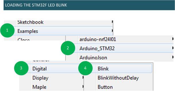
Flashing & loading your first code

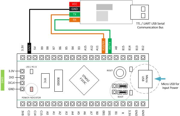
Set the BOOT0 to BOOT1 the board will boot from the system memory which is contains the UART to flash uploader. PRESS RESET Button, after uploading is done your code will start , If you want your code to boot automaticall after the next power-on/reset. set the BOOT0 back to 0 then RESET the board will boot from the program memory.
Demo Code 01
|
1 2 3 4 5 6 7 8 9 10 11 12 13 14 |
#define MyLED PC13 //PC13 LED Onboard void setup() { Serial.begin(9600); pinMode(MyLED, OUTPUT); Serial.println("START"); } void loop() { digitalWrite(MyLED, HIGH); delay(1000); digitalWrite(MyLED, LOW); Serial.println("Hello 14CORE"); } |
Downloads
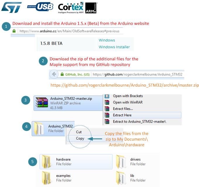
- Download Arduino IDE 1.5.x Version Here | Link
- Download Arduino STM32 Code Libraries Here | Link
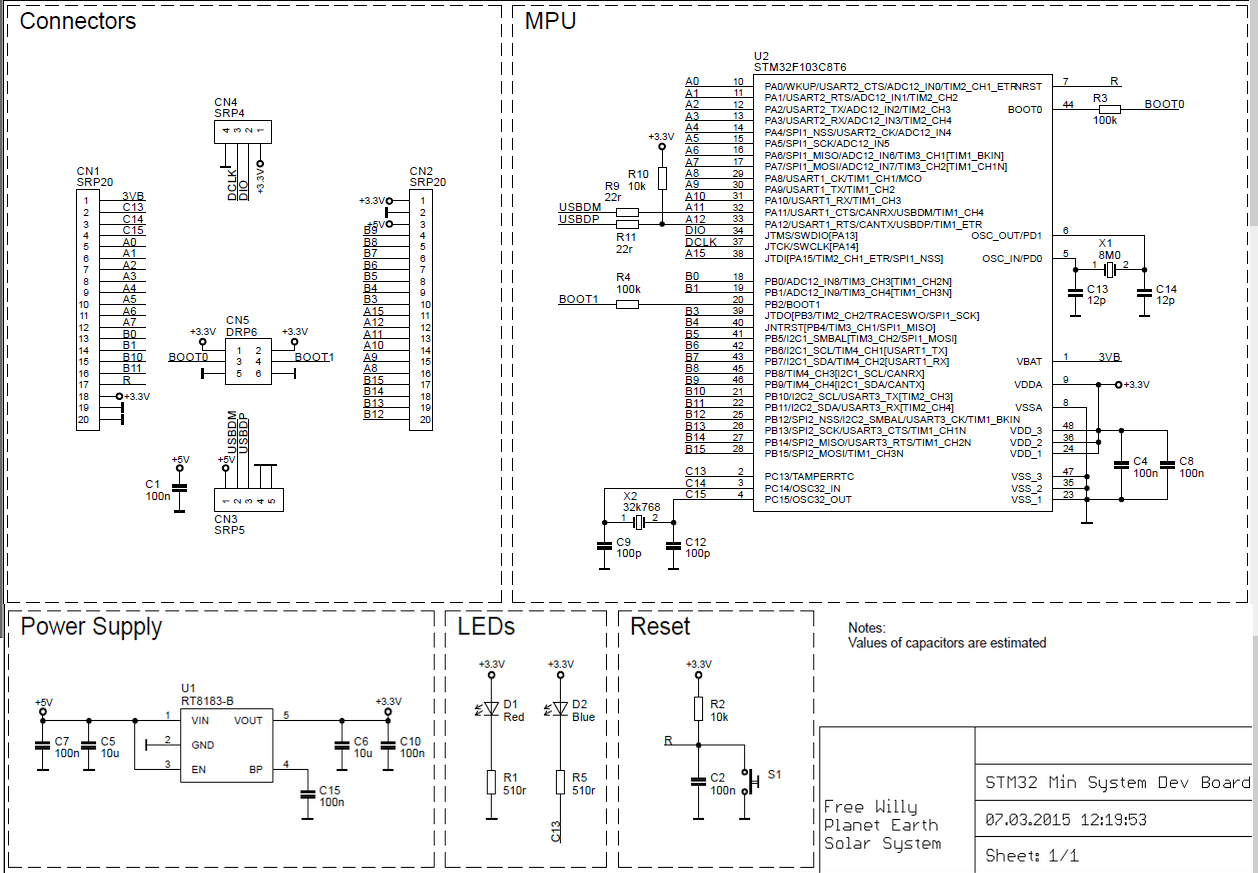
- Download diagram schematics here | JPG
- Download STM32FXX Datasheet | PDF


hi
please help sd library stm32f103
Hi! Hello!. .:)
Please download the library below, sorry for this bloody library needs to reconstruct. concept is almost the same.
I will write an illustration soon reading data from SD card using SPI with STM32fXX.
http://www.14core.com/wp-content/uploads/2017/01/STM32F103-TFT9431-SPI-SD.zip
need library sd arduino stm32f103c8