In this tutorial we will going to wire the HC11 / HC12 UART module a new generation multi-channel embedded wireless transmission module. This module is works on 433 ~ 473 MHz frequency band, you can also set this module works on multiple channel with the stepping of 400 KHz and there are 100 channel can be used. Using the HC11-12 it easy to utilize and customize the wireless data transmission by providing a UART data. It is flexible to set the UART Baud Rate, Frequency, Output Power, Data Rate, Frequency Deviation and Receiving Bandwidth parameters.
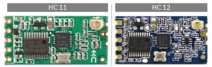
The HC11 wireless communication frequency band is 434MHz in a high transparent FSK transceiver, high output power, high sensitivity and compare to Bluetooth HC05/HC06 it reach to 150~300 Meter on Open Space.
The HC12 maximum transmitting power is 100mW 20dBm, the receiving sensitivity is -117dBm at baud rate 5000bps in the air, communication distance up to 1000m on open space.
Schematics Diagram

Wiring Diagram
As you can see the diagram below its uses two module Note: HC11 does not work with HC12 if you want to build a communication between HC11 & HC12.

AT Command Instructions
|
1 2 3 4 5 6 7 8 9 10 11 12 13 14 15 16 17 18 19 20 21 22 23 24 25 26 27 28 29 30 31 32 33 34 35 36 37 38 39 40 41 42 43 44 45 46 47 48 49 50 51 52 53 54 55 56 57 58 59 60 61 62 63 64 65 66 67 68 69 70 71 72 73 74 75 76 77 78 79 80 81 82 83 84 85 86 87 88 89 90 91 92 93 94 95 96 97 98 99 100 101 102 |
1. AT Test command Example: Send “AT” to module Return: “OK” 2. AT+B Change the serial port baud rate, and it will be valid after exiting from AT mode. The baud rate can be set to: 1200, 2400, 4800, 9600, 19200, 38400, 57600, and 115200. The default value is 9600. Example: Send “AT+B19200” to module to set the serial port baud rate to be 19200. Return: “OK+B19200” 3. AT+C Change the wireless communication channel of module, optional from 001 to 127, and the default value is 001, and the working frequency is 433.4MHz. The channel stepping is 400KHz, and the working frequency of Channel 100 is 473.0MHz. Example: Send “AT+C021” to module to set module channel to be 021 working frequency is 441.4MHz Return: “COK+C021” Note: As the wireless receiving sensitivity of module is relatively high, when the serial port baud rate is greater than 9600bps, five adjacent channels shall be staggered to use. When the serial port baud rate is not greater than 9600bps, in short-distance (within 10m) communication, again, five adjacent channels shall be staggered to use. 4. AT+FUx Set module to wireless UART function. The value of x is optional within 1~ 3. The default mode of module is FU3, and only when serial port function mode of two modules is set to be the same the communication can be realized. F means function, and U means UART Example: Send “AT+FU1” to module configuring module to be come UART FU1. Return: “AT+OK” 5. AT+Px Set transmitting power of module, x is optional from 1 to 8, and the corresponding transmitting power of module. X Value 1 - Transmit Power (dBm) -1 X Value 2 - Transmit Power (dBm) 2 X Value 3 - Transmit Power (dBm) 5 X Value 4 - Transmit Power (dBm) 8 X Value 5 - Transmit Power (dBm) 11 X Value 6 - Transmit Power (dBm) 14 X Value 7 - Transmit Power (dBm) 17 X Value 8 - Transmit Power (dBm) 20 6. AT+Ry Obtain module parameters, y is any letter among B, C, F and P, respectively representing: baud rate, channel, serial port transparent transmission function mode and transmitting power. Example1: Send “AT+RB” to module Return: “OK+B9600” Example2: Send “AT+RC” to module Return: “OK+RC001” 7. AT+RX Obtain all common parameters of module. Return serial port transparent transmission function mode, baud rate, channel, and transmitting power in order. Example: Send “AT+RX” to module Return: “OK+FU3\r\n OK+B9600\r\n OK+C001\r\n OK+RP:+20dBm\r\n” 8. 12. AT+Uxyz Set data bits, check bit and stop bit of serial port communication. Where x is data bit, y is parity check, z is stop bit. Option for parity check: N: No check O: odd E: even Option for stop bit 1: one stop bit 2: two stop bits 3: 1.5 stop bits Example: To send serial port format to be eight data bits,odd parity check, and one stop bit Send “AT+U8O1” to module Return: “OK+U8O1” 9. AT+V Inquire firmware version information of module Example: Send “AT+V” to module Return: “HC-12_V1.1” 10. AT+SLEEP After receiving the command, the module enters sleep mode after exiting from AT mode, and this mode doesn’t allow serial port data transmission. When the module enter AT mode again, the module will exit from sleep mode automatically. Example Send “AT+SLEEP” to module when it’s not needed to transmit data, to save power. Return: “OK+SLEEP” 11. AT+DEFAULT Set serial port baud rate, communication channel, and serial port transparent transmission mode to default value. Example Send “AT+DEFAULT” to module Returns: “OK+DEFAULT” and the default value is restored. 12. AT+UPDATE Put the module in the status of waiting for software update. After sending the command, the module will not respond to command anymore until it is re-energized. |
Downloads
- Download HC11 Documentations |PDF
- Download HC12 Documentations |PDF
- Download HCXX AT-Command-Instruction Set | PDF
- Download HC12- Test Code 1 Updated | HC12 Test Code 2


Where do i get the newest Firmware file for updating the HC-12 module?
Please follow this links you can download 1 / Download 2 for the testing code
It won’t work – you forgot about SET pin. It needs to be grounded to sent AT commands.
/*
Programa : Configurador Modulo HC-11
Funcion : Programa que Envia los Comandos AT al Modulo HC-11 Para Cambiar Sus Parametros
Autor : Roamir Williams
*/
#include
const int PIN_TX = 9;
const int PIN_RX = 10;
const int PIN_SET = 11;
SoftwareSerial ModuloHC11(PIN_RX, PIN_TX);
void setup()
{
pinMode(PIN_SET, OUTPUT); // this pin will Pull-Down the HC-11 to switch module to AT mode
digitalWrite(9, LOW);
Serial.begin(9600);
ModuloHC11.begin(9600);
ImprimirListaComandos();
Serial.println();
Serial.println();
Serial.println(“Enter AT commands:”);
ModuloHC11.write(“AT”);
}
void loop()
{
// Keep reading from HC-11 and send to Arduino Serial Monitor
if (ModuloHC11.available())
Serial.write(ModuloHC11.read());
// Keep reading from Arduino Serial Monitor and send to HC-11
if (Serial.available())
ModuloHC11.write(Serial.read());
}
void ImprimirListaComandos()
{
int Indice = 0;
while((char)pgm_read_byte_near(&Instrucciones[Indice]) != ‘\0’)
{
Serial.print((char)pgm_read_byte_near(&Instrucciones[Indice]));
Indice++;
}
}
Dear sir ,
can you help me ,
how can i sent two or more analog data and received digital output led on off by using HC12 with arduino
please give example codes
Pingback:Extending The Range of 433 MHz with HC-12 / HC-11 & MAX263AXT Radio Signal Booster / Amplifier | 14core.com