In this illustration we’re going to wire the 8bit WS2812B 50-50 which Chainable, addressable LED (Light Emitting Diode) A precise on any vivid colorful light mixing animation, these module as the example for this demonstration we going to control each WS2812B LED using Digital and serial communication. There are two types or version of WS2812 the WS2812 and the WS2812B see the diagram below the difference between the two of theme.
The WS2812 is a family of smart LED light source that control circuit and RGB chip are integrated in a package 50-50 component. It is an onboard intelligent digital port latch and signal reshaping implication drive circuit an effectively ensuring that the pixel point light color are HIGH and consistent.
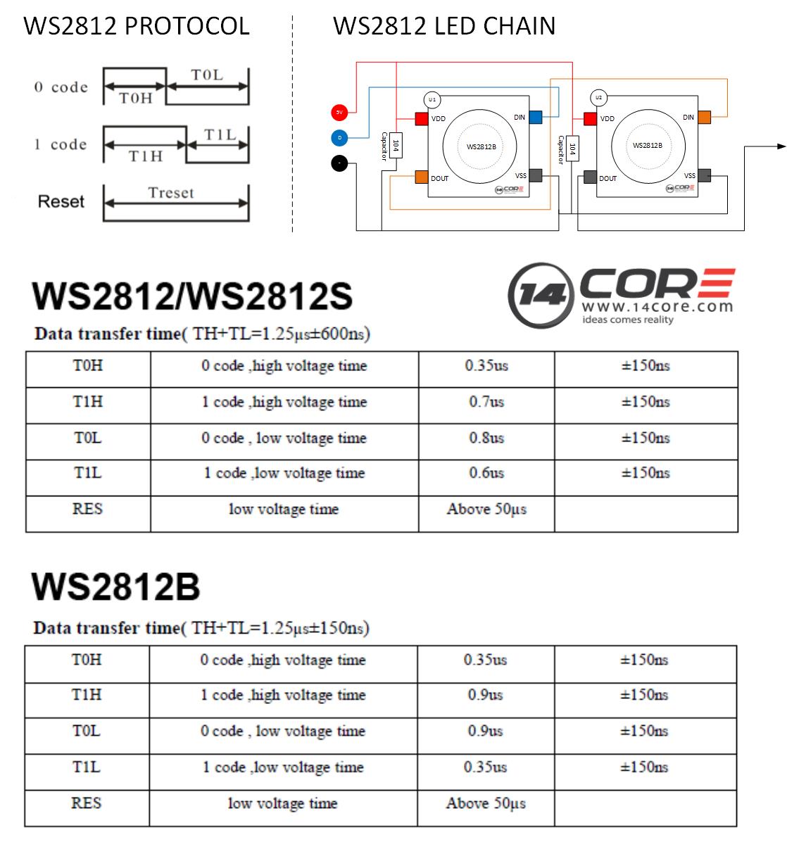
The data transfer protocol uses a single NZR communication mode. When powering the pixel the D-IN port receive data from the microcontroller, the first pixel collect initial a 24bit of data then sent to the internal data latch, the other data which is reshaping by the internal signal, reshaping amplification circuit sent to the next cascade pixel through the DO port.After transmission for each pixel the signal will reduce to 24bit. The pixel adopt an auto reshaping transmit technology, making the pixel cascade number is not limited the signal transmission only depend on the speed of the signal transmission.
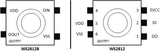
The WS2812B is a new generation of the product based on WS2812. It is not only inherited from the WS2812 but also improve the Integrated Circuit from mechanical arrangement outside & inside to the structure and enhance the stability and efficiency.
Compared to the first version of WS2812 and the new WS2812B they added a reverse protection circuit. The circuit has been reverse the connection of the power supply without any damage to the device and to increase the stability which in effect.
As you can see the mechanical design. You can see the comparison between the two, it is very easy to find the difference between the WS281 and WS2812B the same size but difference is the PIN number they reduced to 4 pin, with the decrease of the spacing between adjacent legs is added.
WS2812 / WS2812B
WS2812 Protocol
Wiring with Arduino
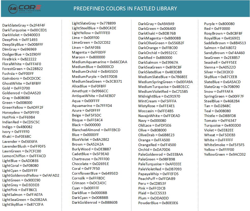
Predefined Colors in FastLED Library
Arduino Sketch Code w/d Fast LED
|
1 2 3 4 5 6 7 8 9 10 11 12 13 14 15 16 17 18 19 20 21 22 23 24 25 26 27 28 29 30 31 32 33 34 35 36 37 38 39 40 41 42 43 44 45 46 47 48 49 50 51 52 53 54 55 56 57 58 59 60 61 62 63 64 65 66 67 68 69 70 71 72 73 74 75 76 77 78 79 |
#include "FastLED.h" // Number of RGB LEDs in the strand #define NUM_LEDS 60 // Define the array of leds CRGB leds[NUM_LEDS]; // Arduino pin used for Data #define PIN 6 void setup() { FastLED.addLeds<NEOPIXEL, PIN, RGB>(leds, NUM_LEDS); } void loop() { // one at a time for(int j = 0; j < 3; j++) { for(int i = 0 ; i < NUM_LEDS; i++ ) { memset(leds, 0, NUM_LEDS * 3); switch(j) { case 0: leds[i].r = 255; break; case 1: leds[i].g = 255; break; case 2: leds[i].b = 255; break; } FastLED.show(); delay(10); } } // growing/receeding bars for(int j = 0; j < 3; j++) { memset(leds, 0, NUM_LEDS * 3); for(int i = 0 ; i < NUM_LEDS; i++ ) { switch(j) { case 0: leds[i].r = 255; break; case 1: leds[i].g = 255; break; case 2: leds[i].b = 255; break; } FastLED.show(); delay(10); } for(int i = NUM_LEDS-1 ; i >= 0; i-- ) { switch(j) { case 0: leds[i].r = 0; break; case 1: leds[i].g = 0; break; case 2: leds[i].b = 0; break; } FastSPI_LED.show(); delay(1); } } // Fade in/fade out for(int j = 0; j < 3; j++ ) { memset(leds, 0, NUM_LEDS * 3); for(int k = 0; k < 256; k++) { for(int i = 0; i < NUM_LEDS; i++ ) { switch(j) { case 0: leds[i].r = k; break; case 1: leds[i].g = k; break; case 2: leds[i].b = k; break; } } FastLED.show(); delay(3); } for(int k = 255; k >= 0; k--) { for(int i = 0; i < NUM_LEDS; i++ ) { switch(j) { case 0: leds[i].r = k; break; case 1: leds[i].g = k; break; case 2: leds[i].b = k; break; } } FastLED.show(); delay(3); } } } |
|
1 2 3 4 5 6 7 8 9 10 11 12 13 14 15 16 17 18 19 20 21 22 23 24 25 26 27 28 29 30 31 32 33 34 35 36 37 38 39 40 41 42 43 44 45 46 47 48 49 50 51 52 53 54 55 56 57 58 59 60 61 62 63 64 65 66 67 68 69 70 71 72 73 74 75 76 77 78 79 80 81 82 83 84 85 86 87 88 89 90 91 92 93 94 95 96 97 98 99 100 101 102 103 104 105 106 107 108 109 110 111 112 113 114 115 116 117 118 119 120 121 122 123 124 125 126 127 128 129 130 131 132 133 134 135 136 137 138 139 140 141 142 143 144 145 146 147 148 149 150 151 152 153 154 155 156 157 158 159 160 161 162 163 164 165 166 167 168 169 170 171 172 173 174 175 176 177 178 179 180 181 182 183 184 185 186 187 188 189 190 191 192 193 194 195 196 197 198 199 200 201 202 203 204 205 206 207 208 209 210 211 212 213 214 215 216 217 218 219 220 221 222 223 224 225 226 227 228 229 230 231 232 233 234 235 236 237 238 239 240 241 242 243 244 245 246 247 248 249 250 251 252 253 254 255 256 257 258 259 260 261 262 263 264 265 266 267 268 269 270 271 272 273 274 275 276 277 278 279 280 281 282 283 284 285 286 287 288 289 290 291 292 293 294 295 296 297 298 299 300 301 302 303 304 305 306 307 308 309 310 311 312 313 314 315 316 317 318 319 320 321 322 323 324 325 326 327 328 329 330 331 332 333 334 335 336 337 338 339 340 341 342 343 344 345 346 347 348 349 350 351 352 353 354 355 356 357 358 359 360 361 362 363 364 365 366 367 368 369 370 371 372 373 374 375 376 377 378 379 380 381 382 383 384 385 386 387 388 389 390 391 392 393 394 395 396 397 398 399 400 401 402 403 404 405 406 407 408 409 410 411 412 413 414 415 416 417 418 419 420 421 422 423 424 425 426 427 428 429 430 431 432 433 434 435 436 437 438 439 440 441 442 443 444 445 446 447 448 449 450 451 452 453 454 455 456 457 458 459 460 461 462 463 464 465 466 467 468 469 470 471 472 473 474 475 476 477 478 479 480 481 482 483 484 485 486 487 488 489 490 491 492 493 494 495 496 497 498 499 500 501 502 503 504 505 506 507 508 509 510 511 512 513 514 515 516 517 518 519 520 521 522 523 524 525 526 527 528 529 530 531 532 533 534 535 536 537 538 539 540 541 542 543 544 545 546 547 548 549 550 551 552 553 554 555 556 557 558 559 560 561 562 563 564 565 566 567 568 569 570 571 572 573 574 575 576 577 578 579 580 581 582 583 584 585 586 587 588 589 590 591 592 593 594 595 596 597 598 599 600 601 602 603 604 605 606 607 608 609 610 611 612 613 614 615 616 617 618 619 620 621 622 623 624 625 626 627 628 629 630 631 632 633 634 635 636 637 638 639 640 641 642 643 644 645 646 647 648 649 650 651 652 653 654 655 656 657 658 659 660 661 662 663 664 665 666 667 668 669 670 671 672 673 674 675 676 677 678 679 680 681 682 683 684 685 686 687 |
#include <FastSPI_LED2.h> //---LED SETUP STUFF #define LED_COUNT 24 #define LED_PIN 13 int BOTTOM_INDEX = 0; int TOP_INDEX = int(LED_COUNT/2); int EVENODD = LED_COUNT%2; struct CRGB leds[LED_COUNT]; int ledsX[LED_COUNT][3]; //-ARRAY FOR COPYING WHATS IN THE LED STRIP CURRENTLY (FOR CELL-AUTOMATA, MARCH, ETC) int ledMode = 3; //-START IN RAINBOW LOOP //---SERIAL/BLUETOOTH SETUP STUFF #define SERIAL_BAUDRATE 9600 byte inbyte; //-SERIAL INPUT BYTE int thisarg; //-SERIAL INPUT ARG //---LED FX VARS int max_bright = 64; //-SET MAX BRIGHTNESS TO 1/4 int idex = 0; //-LED INDEX (0 to LED_COUNT-1 int idx_offset = 0; //-OFFSET INDEX (BOTTOM LED TO ZERO WHEN LOOP IS TURNED/DOESN'T REALLY WORK) int ihue = 0; //-HUE (0-360) static uint8_t startinghue = 0; int ibright = 0; //-BRIGHTNESS (0-255) int isat = 0; //-SATURATION (0-255) int bouncedirection = 0; //-SWITCH FOR COLOR BOUNCE (0-1) float tcount = 0.0; //-INC VAR FOR SIN LOOPS int lcount = 0; //-ANOTHER COUNTING VAR //------------------------------------- UTILITY FXNS -------------------------------------- //---SET THE COLOR OF A SINGLE RGB LED void set_color_led(int adex, int cred, int cgrn, int cblu) { int bdex; if (idx_offset > 0) { //-APPLY INDEX OFFSET bdex = (adex + idx_offset) % LED_COUNT; } else {bdex = adex;} leds[bdex].r = cred; leds[bdex].g = cgrn; leds[bdex].b = cblu; } //---FIND INDEX OF HORIZONAL OPPOSITE LED int horizontal_index(int i) { //-ONLY WORKS WITH INDEX < TOPINDEX if (i == BOTTOM_INDEX) {return BOTTOM_INDEX;} if (i == TOP_INDEX && EVENODD == 1) {return TOP_INDEX + 1;} if (i == TOP_INDEX && EVENODD == 0) {return TOP_INDEX;} return LED_COUNT - i; } //---FIND INDEX OF ANTIPODAL OPPOSITE LED int antipodal_index(int i) { //int N2 = int(LED_COUNT/2); int iN = i + TOP_INDEX; if (i >= TOP_INDEX) {iN = ( i + TOP_INDEX ) % LED_COUNT; } return iN; } //---FIND ADJACENT INDEX CLOCKWISE int adjacent_cw(int i) { int r; if (i < LED_COUNT - 1) {r = i + 1;} else {r = 0;} return r; } //---FIND ADJACENT INDEX COUNTER-CLOCKWISE int adjacent_ccw(int i) { int r; if (i > 0) {r = i - 1;} else {r = LED_COUNT - 1;} return r; } void copy_led_array(){ for(int i = 0; i < LED_COUNT; i++ ) { ledsX[i][0] = leds[i].r; ledsX[i][1] = leds[i].g; ledsX[i][2] = leds[i].b; } } //------------------------LED EFFECT FUNCTIONS------------------------ void one_color_all(int cred, int cgrn, int cblu) { //-SET ALL LEDS TO ONE COLOR for(int i = 0 ; i < LED_COUNT; i++ ) { set_color_led(i, cred, cgrn, cblu); LEDS.show(); delay(1); } } void rainbow_fade(int idelay) { //-m2-FADE ALL LEDS THROUGH HSV RAINBOW ihue++; if (ihue >= 359) {ihue = 0;} for(int idex = 0 ; idex < LED_COUNT; idex++ ) { leds[idex] = CHSV(ihue, 255, 255); } LEDS.show(); delay(idelay); } void rainbow_loop(int istep, int idelay) { //-m3-LOOP HSV RAINBOW idex++; ihue = ihue + istep; if (idex >= LED_COUNT) {idex = 0;} if (ihue >= 359) {ihue = 0;} leds[idex] = CHSV(ihue, 255, 255); LEDS.show(); delay(idelay); } void random_burst(int idelay) { //-m4-RANDOM INDEX/COLOR idex = random(0,LED_COUNT); ihue = random(0,359); leds[idex] = CHSV(ihue, 255, 255); LEDS.show(); delay(idelay); } void color_bounce(int idelay) { //-m5-BOUNCE COLOR (SINGLE LED) if (bouncedirection == 0) { idex = idex + 1; if (idex == LED_COUNT) { bouncedirection = 1; idex = idex - 1; } } if (bouncedirection == 1) { idex = idex - 1; if (idex == 0) { bouncedirection = 0; } } for(int i = 0; i < LED_COUNT; i++ ) { if (i == idex) {set_color_led(i, 255, 0, 0);} else {set_color_led(i, 0, 0, 0);} } LEDS.show(); delay(idelay); } void color_bounceFADE(int idelay) { //-m6-BOUNCE COLOR (SIMPLE MULTI-LED FADE) if (bouncedirection == 0) { idex = idex + 1; if (idex == LED_COUNT) { bouncedirection = 1; idex = idex - 1; } } if (bouncedirection == 1) { idex = idex - 1; if (idex == 0) { bouncedirection = 0; } } int iL1 = adjacent_cw(idex); int iL2 = adjacent_cw(iL1); int iL3 = adjacent_cw(iL2); int iR1 = adjacent_ccw(idex); int iR2 = adjacent_ccw(iR1); int iR3 = adjacent_ccw(iR2); for(int i = 0; i < LED_COUNT; i++ ) { if (i == idex) {set_color_led(i, 255, 0, 0);} else if (i == iL1) {set_color_led(i, 100, 0, 0);} else if (i == iL2) {set_color_led(i, 50, 0, 0);} else if (i == iL3) {set_color_led(i, 10, 0, 0);} else if (i == iR1) {set_color_led(i, 100, 0, 0);} else if (i == iR2) {set_color_led(i, 50, 0, 0);} else if (i == iR3) {set_color_led(i, 10, 0, 0);} else {set_color_led(i, 0, 0, 0);} } LEDS.show(); delay(idelay); } void police_lightsONE(int idelay) { //-m7-POLICE LIGHTS (TWO COLOR SINGLE LED) idex++; if (idex >= LED_COUNT) {idex = 0;} int idexR = idex; int idexB = antipodal_index(idexR); for(int i = 0; i < LED_COUNT; i++ ) { if (i == idexR) {set_color_led(i, 255, 0, 0);} else if (i == idexB) {set_color_led(i, 0, 0, 255);} else {set_color_led(i, 0, 0, 0);} } LEDS.show(); delay(idelay); } void police_lightsALL(int idelay) { //-m8-POLICE LIGHTS (TWO COLOR SOLID) idex++; if (idex >= LED_COUNT) {idex = 0;} int idexR = idex; int idexB = antipodal_index(idexR); set_color_led(idexR, 255, 0, 0); set_color_led(idexB, 0, 0, 255); LEDS.show(); delay(idelay); } void flicker(int thishue, int thissat) { //-m9-FLICKER EFFECT int random_bright = random(0,255); int random_delay = random(10,100); int random_bool = random(0,random_bright); if (random_bool < 10) { for(int i = 0 ; i < LED_COUNT; i++ ) { leds[i] = CHSV(thishue, thissat, random_bright); } LEDS.show(); delay(random_delay); } } void pulse_one_color_all(int ihue, int idelay) { //-m10-PULSE BRIGHTNESS ON ALL LEDS TO ONE COLOR if (bouncedirection == 0) { ibright++; if (ibright >= 255) {bouncedirection = 1;} } if (bouncedirection == 1) { ibright = ibright - 1; if (ibright <= 1) {bouncedirection = 0;} } for(int idex = 0 ; idex < LED_COUNT; idex++ ) { leds[idex] = CHSV(ihue, 255, ibright); } LEDS.show(); delay(idelay); } void pulse_one_color_all_rev(int ihue, int idelay) { //-m11-PULSE SATURATION ON ALL LEDS TO ONE COLOR if (bouncedirection == 0) { isat++; if (isat >= 255) {bouncedirection = 1;} } if (bouncedirection == 1) { isat = isat - 1; if (isat <= 1) {bouncedirection = 0;} } for(int idex = 0 ; idex < LED_COUNT; idex++ ) { leds[idex] = CHSV(ihue, isat, 255); } LEDS.show(); delay(idelay); } void fade_vertical(int ihue, int idelay) { //-m12-FADE 'UP' THE LOOP idex++; if (idex > TOP_INDEX) {idex = 0;} int idexA = idex; int idexB = horizontal_index(idexA); ibright = ibright + 10; if (ibright > 255) {ibright = 0;} leds[idexA] = CHSV(ihue, 255, ibright); leds[idexB] = CHSV(ihue, 255, ibright); LEDS.show(); delay(idelay); } void random_red() { //QUICK 'N DIRTY RANDOMIZE TO GET CELL AUTOMATA STARTED int temprand; for(int i = 0; i < LED_COUNT; i++ ) { temprand = random(0,100); if (temprand > 50) {leds[i].r = 255;} if (temprand <= 50) {leds[i].r = 0;} leds[i].b = 0; leds[i].g = 0; } LEDS.show(); } void rule30(int idelay) { //-m13-1D CELLULAR AUTOMATA - RULE 30 (RED FOR NOW) if (bouncedirection == 0) { random_red(); bouncedirection = 1; } copy_led_array(); int iCW; int iCCW; int y = 100; for(int i = 0; i < LED_COUNT; i++ ) { iCW = adjacent_cw(i); iCCW = adjacent_ccw(i); if (ledsX[iCCW][0] > y && ledsX[i][0] > y && ledsX[iCW][0] > y) {leds[i].r = 0;} if (ledsX[iCCW][0] > y && ledsX[i][0] > y && ledsX[iCW][0] <= y) {leds[i].r = 0;} if (ledsX[iCCW][0] > y && ledsX[i][0] <= y && ledsX[iCW][0] > y) {leds[i].r = 0;} if (ledsX[iCCW][0] > y && ledsX[i][0] <= y && ledsX[iCW][0] <= y) {leds[i].r = 255;} if (ledsX[iCCW][0] <= y && ledsX[i][0] > y && ledsX[iCW][0] > y) {leds[i].r = 255;} if (ledsX[iCCW][0] <= y && ledsX[i][0] > y && ledsX[iCW][0] <= y) {leds[i].r = 255;} if (ledsX[iCCW][0] <= y && ledsX[i][0] <= y && ledsX[iCW][0] > y) {leds[i].r = 255;} if (ledsX[iCCW][0] <= y && ledsX[i][0] <= y && ledsX[iCW][0] <= y) {leds[i].r = 0;} } LEDS.show(); delay(idelay); } void random_march(int idelay) { //-m14-RANDOM MARCH CCW copy_led_array(); int iCCW; leds[0] = CHSV(random(0,360), 255, 255); for(int idex = 1; idex < LED_COUNT ; idex++ ) { iCCW = adjacent_ccw(idex); leds[idex].r = ledsX[iCCW][0]; leds[idex].g = ledsX[iCCW][1]; leds[idex].b = ledsX[iCCW][2]; } LEDS.show(); delay(idelay); } void rwb_march(int idelay) { //-m15-R,W,B MARCH CCW copy_led_array(); int iCCW; idex++; if (idex > 2) {idex = 0;} switch (idex) { case 0: leds[0].r = 255; leds[0].g = 0; leds[0].b = 0; break; case 1: leds[0].r = 255; leds[0].g = 255; leds[0].b = 255; break; case 2: leds[0].r = 0; leds[0].g = 0; leds[0].b = 255; break; } for(int i = 1; i < LED_COUNT; i++ ) { iCCW = adjacent_ccw(i); leds[i].r = ledsX[iCCW][0]; leds[i].g = ledsX[iCCW][1]; leds[i].b = ledsX[iCCW][2]; } LEDS.show(); delay(idelay); } void radiation(int ihue, int idelay) { //-m16-SORT OF RADIATION SYMBOLISH- int N3 = int(LED_COUNT/3); int N6 = int(LED_COUNT/6); int N12 = int(LED_COUNT/12); for(int i = 0; i < N6; i++ ) { //-HACKY, I KNOW... tcount = tcount + .02; if (tcount > 3.14) {tcount = 0.0;} ibright = int(sin(tcount)*255); int j0 = (i + LED_COUNT - N12) % LED_COUNT; int j1 = (j0+N3) % LED_COUNT; int j2 = (j1+N3) % LED_COUNT; leds[j0] = CHSV(ihue, 255, ibright); leds[j1] = CHSV(ihue, 255, ibright); leds[j2] = CHSV(ihue, 255, ibright); } LEDS.show(); delay(idelay); } void color_loop_vardelay() { //-m17-COLOR LOOP (SINGLE LED) w/ VARIABLE DELAY idex++; if (idex > LED_COUNT) {idex = 0;} int di = abs(TOP_INDEX - idex); int t = constrain((10/di)*10, 10, 500); for(int i = 0; i < LED_COUNT; i++ ) { if (i == idex) { leds[i] = CHSV(0, 255, 255); } else { leds[i].r = 0; leds[i].g = 0; leds[i].b = 0; } } LEDS.show(); delay(t); } void white_temps() { //-m18-SHOW A SAMPLE OF BLACK BODY RADIATION COLOR TEMPERATURES int N9 = int(LED_COUNT/9); for (int i = 0; i < LED_COUNT; i++ ) { if (i >= 0 && i < N9) {leds[i].r = 255; leds[i].g = 147; leds[i].b = 41;} //-CANDLE - 1900 if (i >= N9 && i < N9*2) {leds[i].r = 255; leds[i].g = 197; leds[i].b = 143;} //-40W TUNG - 2600 if (i >= N9*2 && i < N9*3) {leds[i].r = 255; leds[i].g = 214; leds[i].b = 170;} //-100W TUNG - 2850 if (i >= N9*3 && i < N9*4) {leds[i].r = 255; leds[i].g = 241; leds[i].b = 224;} //-HALOGEN - 3200 if (i >= N9*4 && i < N9*5) {leds[i].r = 255; leds[i].g = 250; leds[i].b = 244;} //-CARBON ARC - 5200 if (i >= N9*5 && i < N9*6) {leds[i].r = 255; leds[i].g = 255; leds[i].b = 251;} //-HIGH NOON SUN - 5400 if (i >= N9*6 && i < N9*7) {leds[i].r = 255; leds[i].g = 255; leds[i].b = 255;} //-DIRECT SUN - 6000 if (i >= N9*7 && i < N9*8) {leds[i].r = 201; leds[i].g = 226; leds[i].b = 255;} //-OVERCAST SKY - 7000 if (i >= N9*8 && i < LED_COUNT) {leds[i].r = 64; leds[i].g = 156; leds[i].b = 255;}//-CLEAR BLUE SKY - 20000 } LEDS.show(); delay(100); } void sin_bright_wave(int ihue, int idelay) { //-m19-BRIGHTNESS SINE WAVE for(int i = 0; i < LED_COUNT; i++ ) { tcount = tcount + .1; if (tcount > 3.14) {tcount = 0.0;} ibright = int(sin(tcount)*255); leds[i] = CHSV(ihue, 255, ibright); LEDS.show(); delay(idelay); } } void pop_horizontal(int ihue, int idelay) { //-m20-POP FROM LEFT TO RIGHT UP THE RING int ix; if (bouncedirection == 0) { bouncedirection = 1; ix = idex; } else if (bouncedirection == 1) { bouncedirection = 0; ix = horizontal_index(idex); idex++; if (idex > TOP_INDEX) {idex = 0;} } for(int i = 0; i < LED_COUNT; i++ ) { if (i == ix) { leds[i] = CHSV(ihue, 255, 255); } else { leds[i].r = 0; leds[i].g = 0; leds[i].b = 0; } } LEDS.show(); delay(idelay); } void quad_bright_curve(int ihue, int idelay) { //-m21-QUADRATIC BRIGHTNESS CURVER int ax; for(int x = 0; x < LED_COUNT; x++ ) { if (x <= TOP_INDEX) {ax = x;} else if (x > TOP_INDEX) {ax = LED_COUNT-x;} int a = 1; int b = 1; int c = 0; int iquad = -(ax*ax*a)+(ax*b)+c; //-ax2+bx+c int hquad = -(TOP_INDEX*TOP_INDEX*a)+(TOP_INDEX*b)+c; ibright = int((float(iquad)/float(hquad))*255); leds[x] = CHSV(ihue, 255, ibright); } LEDS.show(); delay(idelay); } void flame() { //-m22-FLAMEISH EFFECT int idelay = random(0,35); float hmin = 0.1; float hmax = 45.0; float hdif = hmax-hmin; int randtemp = random(0,3); float hinc = (hdif/float(TOP_INDEX))+randtemp; int ihue = hmin; for(int i = 0; i < TOP_INDEX; i++ ) { ihue = ihue + hinc; leds[i] = CHSV(ihue, 255, 255); int ih = horizontal_index(i); leds[ih] = CHSV(ihue, 255, 255); leds[TOP_INDEX].r = 255; leds[TOP_INDEX].g = 255; leds[TOP_INDEX].b = 255; LEDS.show(); delay(idelay); } } void rainbow_vertical(int istep, int idelay) { //-m23-RAINBOW 'UP' THE LOOP idex++; if (idex > TOP_INDEX) {idex = 0;} ihue = ihue + istep; if (ihue > 359) {ihue = 0;} int idexA = idex; int idexB = horizontal_index(idexA); leds[idexA] = CHSV(ihue, 255, 255); leds[idexB] = CHSV(ihue, 255, 255); LEDS.show(); delay(idelay); } void pacman(int idelay) { //-m24-REALLY TERRIBLE PACMAN CHOMPING EFFECT int s = int(LED_COUNT/4); lcount++; if (lcount > 5) {lcount = 0;} if (lcount == 0) { for(int i = 0 ; i < LED_COUNT; i++ ) {set_color_led(i, 255, 255, 0);} } if (lcount == 1 || lcount == 5) { for(int i = 0 ; i < LED_COUNT; i++ ) {set_color_led(i, 255, 255, 0);} leds[s].r = 0; leds[s].g = 0; leds[s].b = 0;} if (lcount == 2 || lcount == 4) { for(int i = 0 ; i < LED_COUNT; i++ ) {set_color_led(i, 255, 255, 0);} leds[s-1].r = 0; leds[s-1].g = 0; leds[s-1].b = 0; leds[s].r = 0; leds[s].g = 0; leds[s].b = 0; leds[s+1].r = 0; leds[s+1].g = 0; leds[s+1].b = 0;} if (lcount == 3) { for(int i = 0 ; i < LED_COUNT; i++ ) {set_color_led(i, 255, 255, 0);} leds[s-2].r = 0; leds[s-2].g = 0; leds[s-2].b = 0; leds[s-1].r = 0; leds[s-1].g = 0; leds[s-1].b = 0; leds[s].r = 0; leds[s].g = 0; leds[s].b = 0; leds[s+1].r = 0; leds[s+1].g = 0; leds[s+1].b = 0; leds[s+2].r = 0; leds[s+2].g = 0; leds[s+2].b = 0;} LEDS.show(); delay(idelay); } void strip_march_cw(int idelay) { //-m50-MARCH STRIP CW copy_led_array(); int iCCW; for(int i = 0; i < LED_COUNT; i++ ) { iCCW = adjacent_ccw(i); leds[i].r = ledsX[iCCW][0]; leds[i].g = ledsX[iCCW][1]; leds[i].b = ledsX[iCCW][2]; } LEDS.show(); delay(idelay); } void strip_march_ccw(int idelay) { //-m51-MARCH STRIP CCW copy_led_array(); int iCW; for(int i = 0; i < LED_COUNT; i++ ) { iCW = adjacent_cw(i); leds[i].r = ledsX[iCW][0]; leds[i].g = ledsX[iCW][1]; leds[i].b = ledsX[iCW][2]; } LEDS.show(); delay(idelay); } void new_rainbow_loop(int idelay){ //-m88-RAINBOW FADE FROM FAST_SPI2 ihue -= 1; fill_rainbow( leds, LED_COUNT, ihue ); LEDS.show(); delay(idelay); } void demo_mode(){ int r = 10; for(int i=0; i<r*3; i++) {one_color_all(255,255,255);} for(int i=0; i<r*25; i++) {rainbow_fade(20);} for(int i=0; i<r*20; i++) {rainbow_loop(10, 20);} for(int i=0; i<r*20; i++) {random_burst(20);} for(int i=0; i<r*12; i++) {color_bounce(20);} for(int i=0; i<r*12; i++) {color_bounceFADE(40);} for(int i=0; i<r*6; i++) {police_lightsONE(40);} for(int i=0; i<r*5; i++) {police_lightsALL(40);} for(int i=0; i<r*40; i++) {flicker(160, 50);} for(int i=0; i<r*50; i++) {pulse_one_color_all(0, 10);} for(int i=0; i<r*35; i++) {pulse_one_color_all_rev(0, 10);} for(int i=0; i<r*5; i++) {fade_vertical(240, 60);} random_red(); for(int i=0; i<r*5; i++) {rule30(100);} for(int i=0; i<r*8; i++) {random_march(30);} for(int i=0; i<r*5; i++) {rwb_march(80);} one_color_all(0,0,0); for(int i=0; i<r*15; i++) {radiation(360, 60);} for(int i=0; i<r*15; i++) {color_loop_vardelay();} for(int i=0; i<r*5; i++) {white_temps();} for(int i=0; i<r; i++) {sin_bright_wave(240, 35);} for(int i=0; i<r*5; i++) {pop_horizontal(0, 100);} for(int i=0; i<r*4; i++) {quad_bright_curve(240, 100);} one_color_all(0,0,0); for(int i=0; i<r*3; i++) {flame();} for(int i=0; i<r*10; i++) {pacman(50);} for(int i=0; i<r*15; i++) {rainbow_vertical(15, 50);} for(int i=0; i<r*3; i++) {strip_march_ccw(100);} for(int i=0; i<r*3; i++) {strip_march_cw(100);} for(int i=0; i<r*3; i++) {one_color_all(255,0,0);} for(int i=0; i<r*3; i++) {one_color_all(0,255,0);} for(int i=0; i<r*3; i++) {one_color_all(0,0,255);} for(int i=0; i<r*3; i++) {one_color_all(255,255,0);} for(int i=0; i<r*3; i++) {one_color_all(0,255,255);} for(int i=0; i<r*3; i++) {one_color_all(255,0,255);} for(int i=0; i<r*120; i++) {new_rainbow_loop(5);} } //void hsv2rgb_raw(const struct CHSV * phsv, struct CRGB * prgb, int numLeds) //void hsv2rgb_rainbow( const struct CHSV* phsv, struct CRGB * prgb, int numLeds) //void hsv2rgb_spectrum( const struct CHSV* phsv, struct CRGB * prgb, int numLeds) //void fill_solid(struct CRGB * pFirstLED, int numToFill, const struct CRGB& color) //void fill_rainbow( struct CRGB * pFirstLED, int numToFill, uint8_t initialhue, uint8_t deltahue ) //------------------SETUP------------------ void setup() { Serial.begin(SERIAL_BAUDRATE); // SETUP HARDWARE SERIAL (USB) LEDS.setBrightness(max_bright); // SET BRIGHTNESS TO 1/4 POWER //LEDS.addLeds<SM16716>(leds, LED_COUNT); //LEDS.addLeds<UCS1903, 13>(leds, LED_COUNT); //LEDS.addLeds<LPD8806>(leds, LED_COUNT)->clearLeds(300); //LEDS.addLeds<LPD8806, BGR>(leds, LED_COUNT); //LEDS.addLeds<LPD8806, 10, 11>(leds, LED_COUNT); //LEDS.addLeds<TM1809, 13>(leds, LED_COUNT); //LEDS.addLeds<TM1803, 13>(leds, LED_COUNT); //LEDS.addLeds<WS2801>(leds, LED_COUNT); //LEDS.addLeds<WS2801, 11, 13, BGR, DATA_RATE_MHZ(3)>(leds, LED_COUNT); //LEDS.addLeds<WS2801, RBG>(leds, LED_COUNT); LEDS.addLeds<WS2811, LED_PIN, GRB>(leds, LED_COUNT); //LEDS.addLeds<WS2811, 11>(leds, LED_COUNT); //LEDS.addLeds<WS2811, 13, BRG>(leds, LED_COUNT); //LEDS.addLeds<WS2811, 13>(leds, LED_COUNT); one_color_all(0,0,0); //-CLEAR STRIP LEDS.show(); Serial.println("---SETUP COMPLETE---"); } //------------------MAIN LOOP------------------ void loop() { if (ledMode == 0) {one_color_all(0,0,0);} //---STRIP OFF if (ledMode == 1) {one_color_all(255,255,255);} //---STRIP SOLID WHITE if (ledMode == 2) {rainbow_fade(20);} //---STRIP RAINBOW FADE if (ledMode == 3) {rainbow_loop(5, 20);} //---RAINBOW LOOP if (ledMode == 4) {random_burst(20);} //---RANDOM if (ledMode == 5) {color_bounce(20);} //---CYLON v1 if (ledMode == 6) {color_bounceFADE(20);} //---CYLON v2 if (ledMode == 7) {police_lightsONE(40);} //---POLICE LIGHTS SINGLE if (ledMode == 8) {police_lightsALL(40);} //---POLICE LIGHTS SOLID if (ledMode == 9) {flicker(160,50);} //---STRIP FLICKER if (ledMode == 10) {pulse_one_color_all(0, 10);} //---PULSE COLOR BRIGHTNESS if (ledMode == 11) {pulse_one_color_all_rev(0, 10);} //---PULSE COLOR SATURATION if (ledMode == 12) {fade_vertical(240, 60);} //---VERTICAL SOMETHING if (ledMode == 13) {rule30(100);} //---CELL AUTO - RULE 30 (RED) if (ledMode == 14) {random_march(30);} //---MARCH RANDOM COLORS if (ledMode == 15) {rwb_march(50);} //---MARCH RWB COLORS if (ledMode == 16) {radiation(360, 60);} //---RADIATION SYMBOL (OR SOME APPROXIMATION) if (ledMode == 17) {color_loop_vardelay();} //---VARIABLE DELAY LOOP if (ledMode == 18) {white_temps();} //---WHITE TEMPERATURES if (ledMode == 19) {sin_bright_wave(240, 35);} //---SIN WAVE BRIGHTNESS if (ledMode == 20) {pop_horizontal(0, 100);} //---POP LEFT/RIGHT if (ledMode == 21) {quad_bright_curve(240, 100);} //---QUADRATIC BRIGHTNESS CURVE if (ledMode == 22) {flame();} //---FLAME-ISH EFFECT if (ledMode == 23) {rainbow_vertical(10, 20);} //---VERITCAL RAINBOW if (ledMode == 24) {pacman(100);} //---PACMAN if (ledMode == 50) {strip_march_ccw(100);} //---MARCH WHATEVERS ON THE STRIP NOW CCW if (ledMode == 51) {strip_march_cw(100);} //---MARCH WHATEVERS ON THE STRIP NOW CW if (ledMode == 88) {new_rainbow_loop(5);} //---RAINBOW FADE FROM FAST_SPI CODE if (ledMode == 101) {one_color_all(255,0,0);} //---101- STRIP SOLID RED if (ledMode == 102) {one_color_all(0,255,0);} //---102- STRIP SOLID GREEN if (ledMode == 103) {one_color_all(0,0,255);} //---103- STRIP SOLID BLUE if (ledMode == 104) {one_color_all(255,255,0);} //---104- STRIP SOLID YELLOW if (ledMode == 105) {one_color_all(0,255,255);} //---105- STRIP SOLID TEAL? if (ledMode == 106) {one_color_all(255,0,255);} //---106- STRIP SOLID VIOLET? if (ledMode == 888) {demo_mode();} //---CYCLE MODES (BLOCKS SERIAL INPUT) //---PROCESS SERIAL COMMANDS AND ARGS if (Serial.available() > 0) { inbyte = Serial.read(); if (inbyte == 109) { //---"m" - SET LED FX MODE thisarg = Serial.parseInt(); Serial.print("SET NEW MODE: "); Serial.println(thisarg); bouncedirection = 0; ledMode = thisarg; } if (inbyte == 108) { //---"l" - SET SINGLE LED VALUE (BROKE) int thisindex = Serial.parseInt(); int thisRED = Serial.parseInt(); int thisGRN = Serial.parseInt(); int thisBLU = Serial.parseInt(); set_color_led(thisindex, thisRED, thisGRN, thisBLU); Serial.print("SET LED COLOR: "); //Serial.println(thisindex, thisRED, thisGRN, thisBLU); } if (inbyte == 98) { //---"b" - SET MAX BRIGHTNESS max_bright = Serial.parseInt(); LEDS.setBrightness(max_bright); Serial.print("SET MAX BRIGHTNESS: "); Serial.println(max_bright); } } } |
Downloads
Download FASTLED Code Library | Zip
Download Adafruit NeoPixel Code Library | Zip
Driving Thousand of LED Strip? Download OctoWS2811 | Zip


Is diagram correct,
Seems that you are showing vdd and vss connected together on 2 LEDs.
I thought vdd would go to vdd and vss to vss , to ground and +5v respectively.
Diagram has been updated. please refer to the WS128 & WS128B datasheet for further details.
Thanks & Regards
Hello,
I would like to know how do you send the commands through the serial monitor.
I know by typing m23 I get an led effect. But when I type l,100,255,000,255 I don’t see the color change.
Could you please help me with this?
Thanks!
Hi Wilson, just follow the code below. :)
—————————————————
#include
#include
#define signalOutRed 3 // Output Pin
#define signalOutGreen 5 // Output Pin
#define signalOutBlue 6 // Output Pin
SerialCommand ownSerialCommand; // Your Serial Command object
void setup()
{
Serial.begin(9600);
pinMode(signalOutRed,OUTPUT);
pinMode(signalOutGreen,OUTPUT);
pinMode(signalOutBlue,OUTPUT);
//This a callbacks for SerialCommand commands
ownSerialCommand.addCommand(“ON”,sON); // Turns LED on
ownSerialCommand.addCommand(“OFF”,sOFF); // Turns LED off
ownSerialCommand.addCommand(“RED”, sRED); // Echos the string argument back
ownSerialCommand.addCommand(“GREEN”,sGREEN);
ownSerialCommand.addCommand(“RED”, sBLUE);
ownSerialCommand.addDefaultHandler(noCommand); // Handler for command that isn’t matched
Serial.println(“14CORE | Led Strip Serial Command Test Code”);
delay(1000)
}
void loop()
{
ownSerialCommand.readSerial(); // We don’t do much, just process serial commands
}
void sON()
{
Serial.println(“Led Strip On”);
analogWrite(signalOutRed, 0);
analogWrite(signalOutGreen, 0);
analogWrite(signalOutBlue, 0);
}
void sOFF()
{
Serial.println(“Led Strip On”);
analogWrite(signalOutRed, 255);
analogWrite(signalOutGreen, 255);
analogWrite(signalOutBlue, 255);
}
// Change the value of each color from 0 to 255 to generate your own color of choice
void sRED()
{
Serial.println(“Led Strip Color Blue”);
analogWrite(signalOutRed, 255);
analogWrite(signalOutGreen, 0);
analogWrite(signalOutRed, 0);
}
void sGREEN()
{
Serial.println(“Led Strip Color Blue”);
analogWrite(signalOutRed, 0);
analogWrite(signalOutGreen, 255);
analogWrite(signalOutBlue, 0);
}
void sBLUE()
{
Serial.println(“Led Strip Color Blue”);
analogWrite(signalOutRed, 0);
analogWrite(signalOutGreen, 0);
analogWrite(signalOutRed, 255);
}
void noCommand()
{
Serial.println(“No Command Available”);
}