AS5600 is a 12-bit high-resolution programmable contactless magnetic rotary position sensor, this sensor can be used as a magnetically driven potentiometer or magnetic encoder. however, compared to a traditional potentiometer or an encoder the AS5600 has significant advantages. AS5600 is a high-precision non-contact with no rotation angle limitation. these advantages make it suitable for non-contact angle measurements applications such as robotic arms, motor closed-loop controllers, machine axis positioning devices, waterproof controllers, motor controllers, Automotive, DJ Console, Musical Instruments and much more.
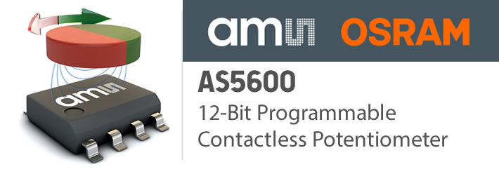
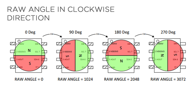
AS5600 is driven by i2C and PWM (Pulse with Modulation) Analog Output and it has a great flexible angular excursion with maximum programmable angles from 18° up to 360° This device is based on the Hall Effect concept that has an integrated Hall sensor that can detect changes in the direction of the magnetic field, including no limitations on angle rotation. The magnetism signal transmission is amplified by the integrated amplifier with the aid of the integrated 12-bit Analog to Digital converter. moreover. The AS5600 can output at 4096 positions per second and this output is selectable by either using the i2C interface or output from RAW data using PWM / Analog Wave vai AOUT pin, additionally, the maximum angle is also programmable and you can set the maximum angle from 18 degrees to 360 degrees it means that the measured angular accuracy is limited up to 18/4096 in pulse. This device is similar to MALEXIS MLX90324 Angle Sensor, However, comparing these two device the AS5600 is it has an i2C interface.
POSITIONING
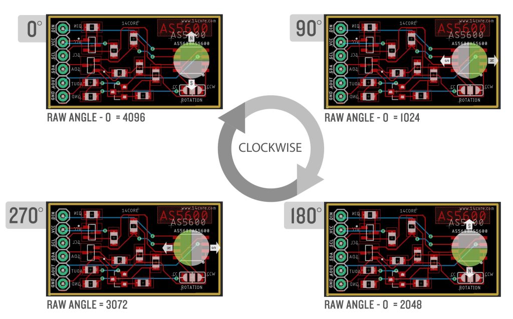
There is 2 direction to be watched CCW (CounterClockWise) & CW (Clockwise) This sensor allows you to control the direction of the magnet and depends on the rotation of the magnet which is configured, as you can see in the diagram we place a JUMPER to pin DIR for your desired rotation ether Clockwise or Counterclockwise if the DIR PIN = 0 then expected that the rotation will be Clockwise on the other hand if the DIR PIN is sent to 1 then it should Counterclockwise.
MAGNETISM
The AS5600 needs or requires a magnetic field component to work, and this magnetic component symbolizes Bz perpendicular to the sensitive area on the AS5600 chip. The hall element circles of the magnetic field Bz should be sine-shaped. moreover, the magnetic field gradient of Bz and the radius of the circle should be in the linear range of the magnet to eliminate the displacement error by the differential measuring principle.
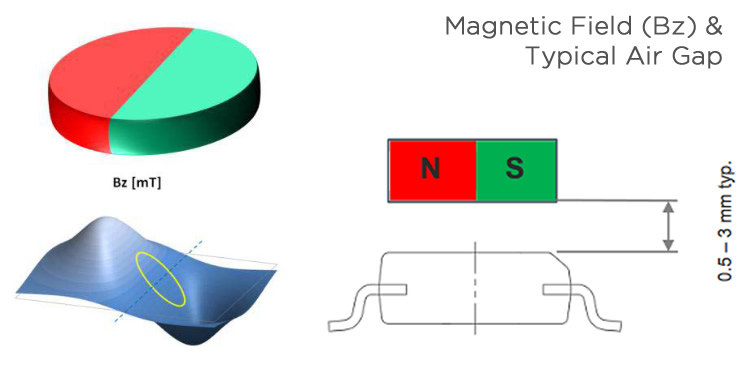
As you can see the typical air gap between the sensor and the magnet is between 0.5 mm and 3 mm depending on your chosen magnet. However, a larger and stronger magnet allows a large air gap between the sensor and the physical magnet. Using an AGC (Auto Gain Control) value is in the center of its range. The maximum allowance displacement of the rotation axis of the magnet from the center of the package is 0.25 mm when using a magnet with a diameter of 6 mm. To learn more about this sensor please read and follow the datasheet below.
Requirements
- Arduino IDE | PlatformIO
- Test Boards :
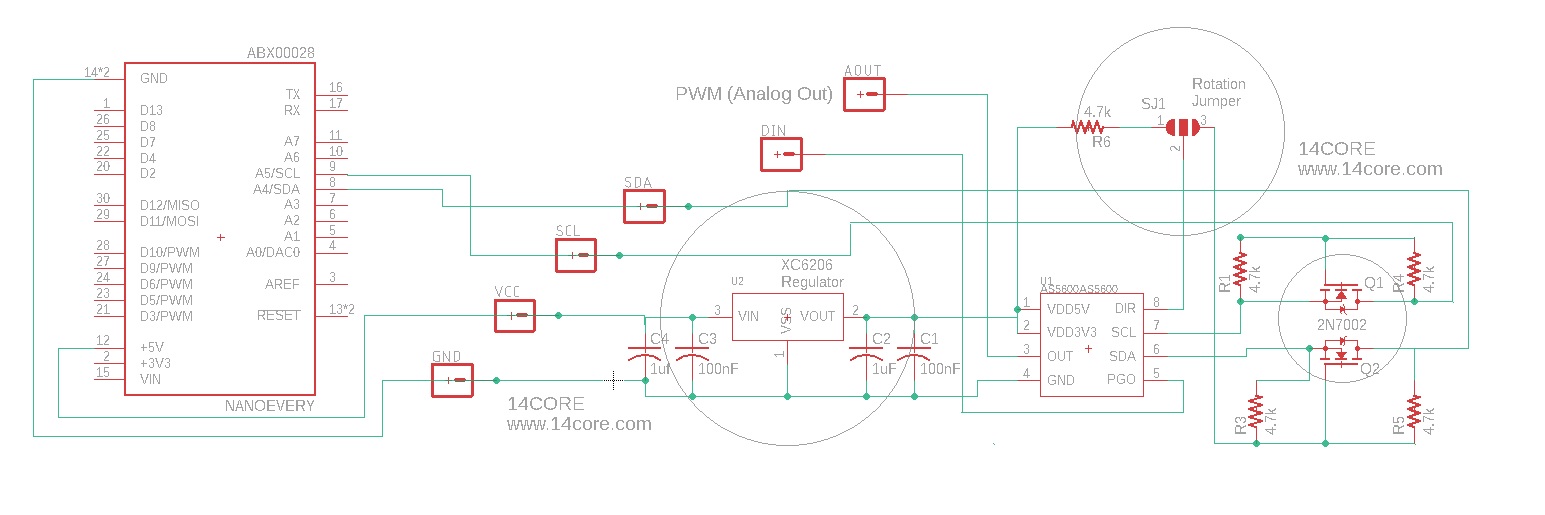
- Note: The Diagram below is using NANOEVERY @ ATMega4809 (please refer to your MCU’s respective pin-outs & bus configuration)
- AS5600 12-Bit Programmable Contact-less Potentiometer
- N-Channel enhancement mode MOSFET
- XC6206 Voltage Regulator
- Resistors (See below diagram for required value & alternatives package)
- Capacitor(See below diagram for required value & alternatives package)
Wiring Diagram / Schematics
Sketch Source Code
|
1 2 3 4 5 6 7 8 9 10 11 12 13 14 15 16 17 18 19 20 21 22 23 24 25 26 27 28 29 30 31 32 33 34 35 36 37 38 39 40 41 42 43 44 45 46 |
#include <Wire.h> #include <AS5600.h> //This library can be downloaded on our download section #ifdef ARDUINO_SAMD_VARIANT_COMPLIANCE #define SERIAL SerialUSB #define SYS_VOL 3.3 #else #define SERIAL Serial #define SYS_VOL 5 #endif AMS_5600 ams5600; int ang, lang = 0; void setup() { SERIAL.begin(115200); Wire.begin(); SERIAL.println("14CORE | AS5600 TEST CODE ( Reading Angles )"); SERIAL.println("Initializing .............................. "); if(ams5600.detectMagnet() == 0 ){ while(1){ if(ams5600.detectMagnet() == 1 ){ SERIAL.print("Current Magnitude: "); SERIAL.println(ams5600.getMagnitude()); break; } else{ /* Make it sure your magnet is place at the top of the AS5600 sensor distance of 0.5 mm */ SERIAL.println("ERROR : Can not detect magnet "); } delay(1000); } } } float convertRawAngleToDegrees(word newAngle) { /* Raw data reports 0 - 4095 segments, which is 0.087 of a degree */ float retVal = newAngle * 0.087; return retVal; } void loop() { SERIAL.println(String(convertRawAngleToDegrees(ams5600.getRawAngle()),DEC)); } |
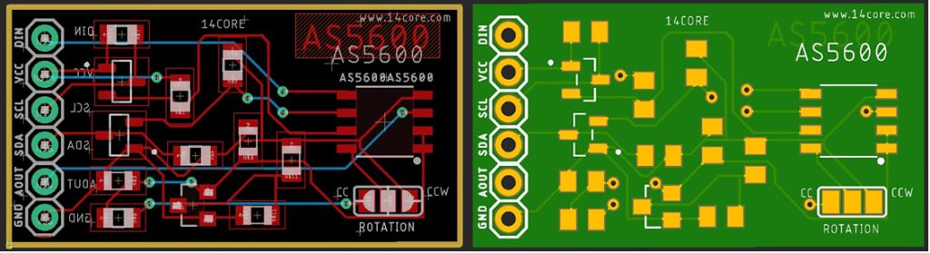
PCB Milling / Gerber