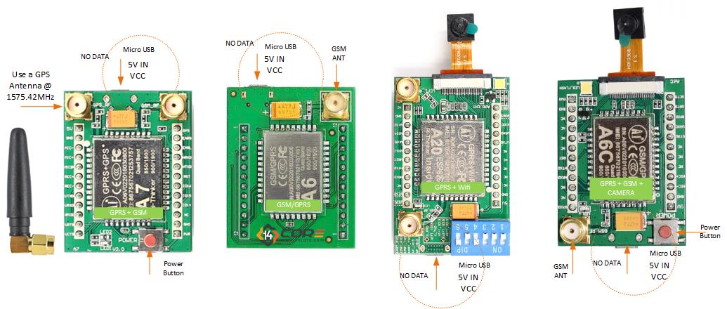
This is A7, A6C, and A6 is a GSM/GPRS/GPS Module that Supports GSM, GPRS, and GPS Quad-Band 850/900/1800/1900 MHz 2G GSM network worldwide with an SMS, GPRS Class 10 Data Service, and GPS feature and supports digital audio and analog audio support for HR, FR, EFR, AMR speech coding, there is another module that comes from this series the A2 & A20.
A2/A20 is GSM/GPRS/GPS + WIFI with ESP8266/8285 Wi-Fi IC onboard, GSM / GPRS four frequency bands including 850, 900, 1800, 1900MHz and it has four working mode the GPRS mode, Wi-Fi mode, both mode, Wi-Fi control GPRS and camera mode. Use ESP8266/8285 secondary UART port that required a code to drive the ESP8266/ESP8285. The A2/A20 you can simply develop a wireless GPS tracking device or a monitoring device can be used in industrial, agricultural monitoring, outdoor monitoring, intelligent home appliance, driving test, fingerprint/face machine, and video doorbell, etc. another function of A6C and A20 is can capture a photo via GPRS or Wi-Fi switch transmission. The A7, A6C, A6, A20 module is controlled by using AT command via UART supplied by 3.3v / 4.2v logic level.
Required Components
- Arduino Microcontrollers, Teensy, ESP8266, ATMEGA328 16/12, ATMEGA32u4 16/8/ MHz, ESP8266, ATMEGA250 16 MHz, ATSAM3x8E, ATSAM21D, ATTINY8516/8 MHz (Note: The Diagram below is using NANO. If you’re using other MCU please refer to the respective pin-outs.
- USB TTL/UART
- A2 / A7 / A6C / A6 Module
- Jumper Wire / DuPont Wire
- Solder Less Bread Board
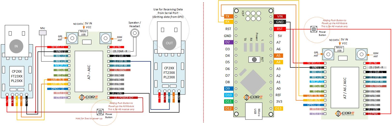
Wiring Diagram for A7 / A6C / A6
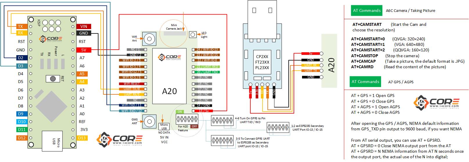
Wiring Diagram for A2 / A20
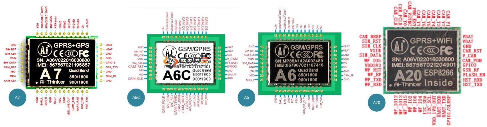
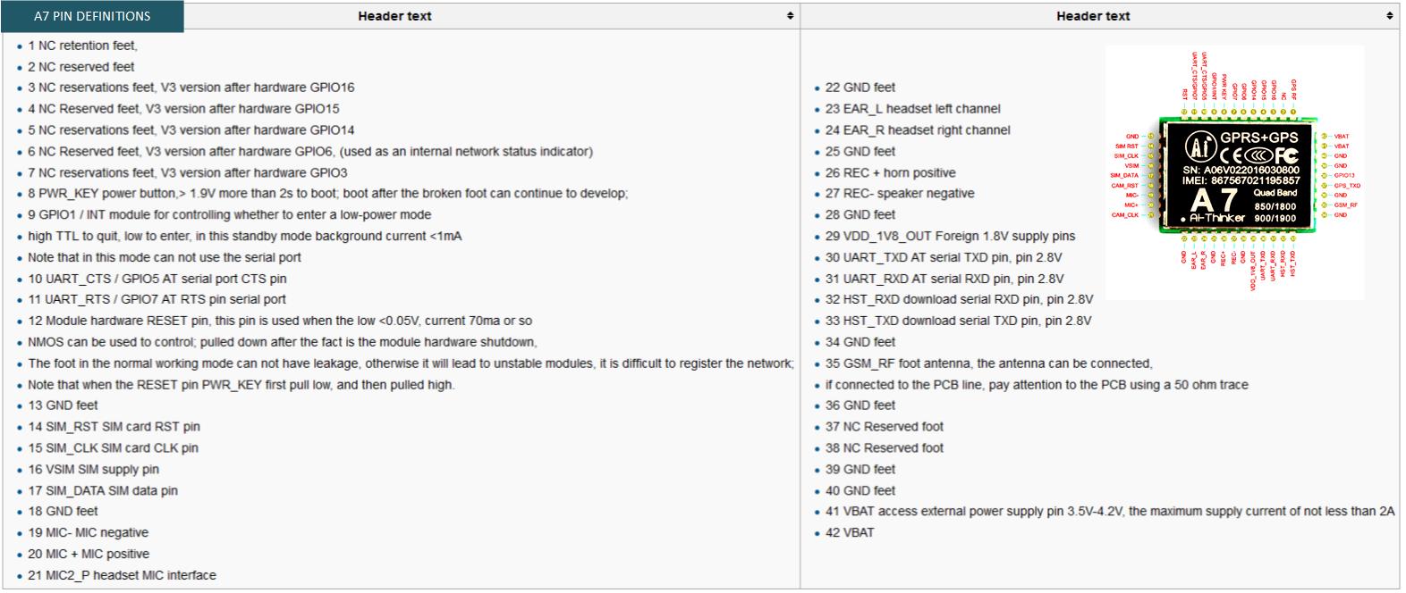
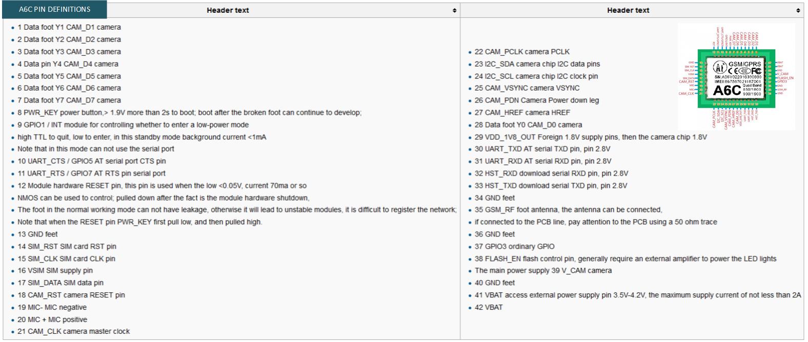
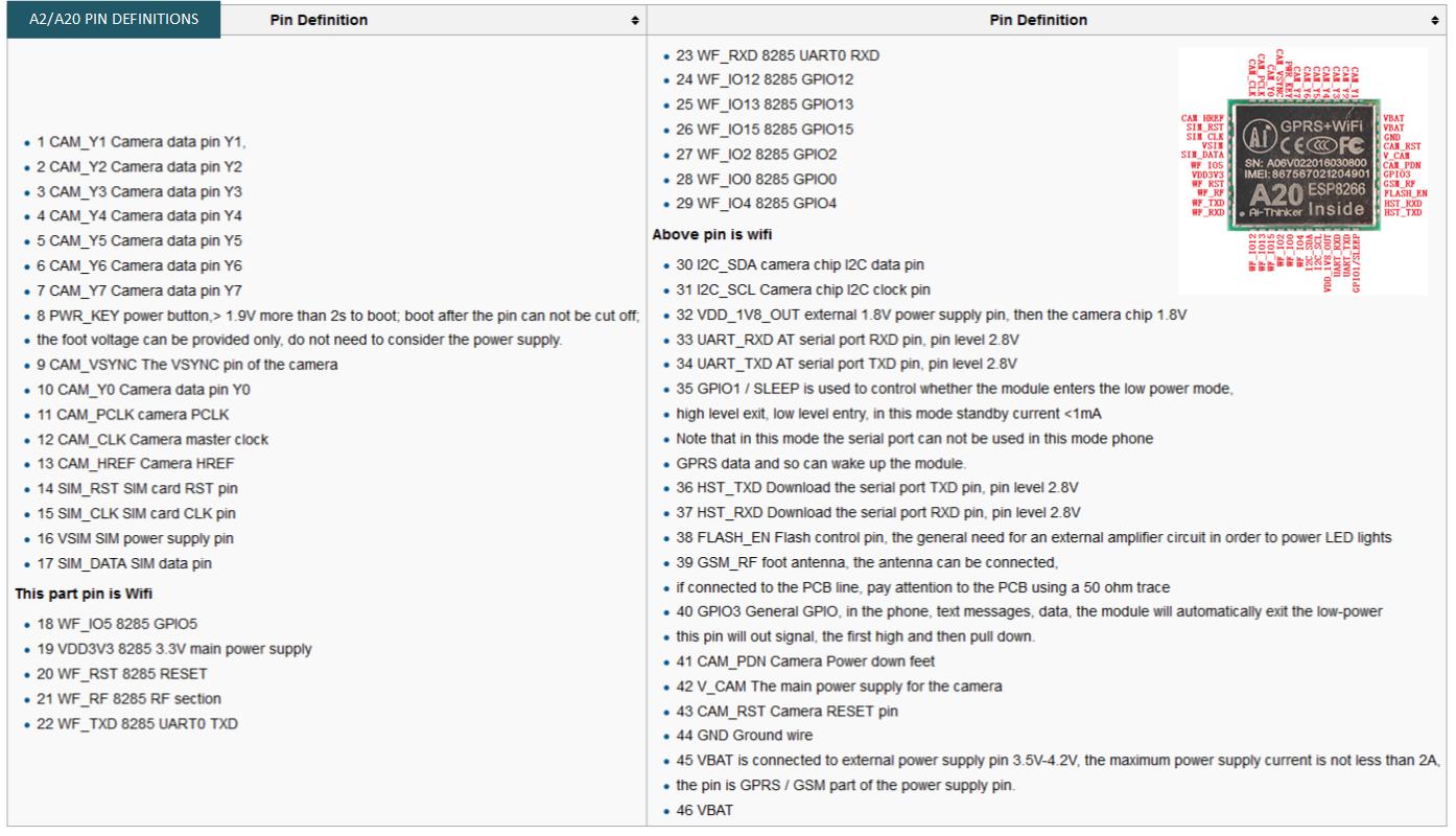
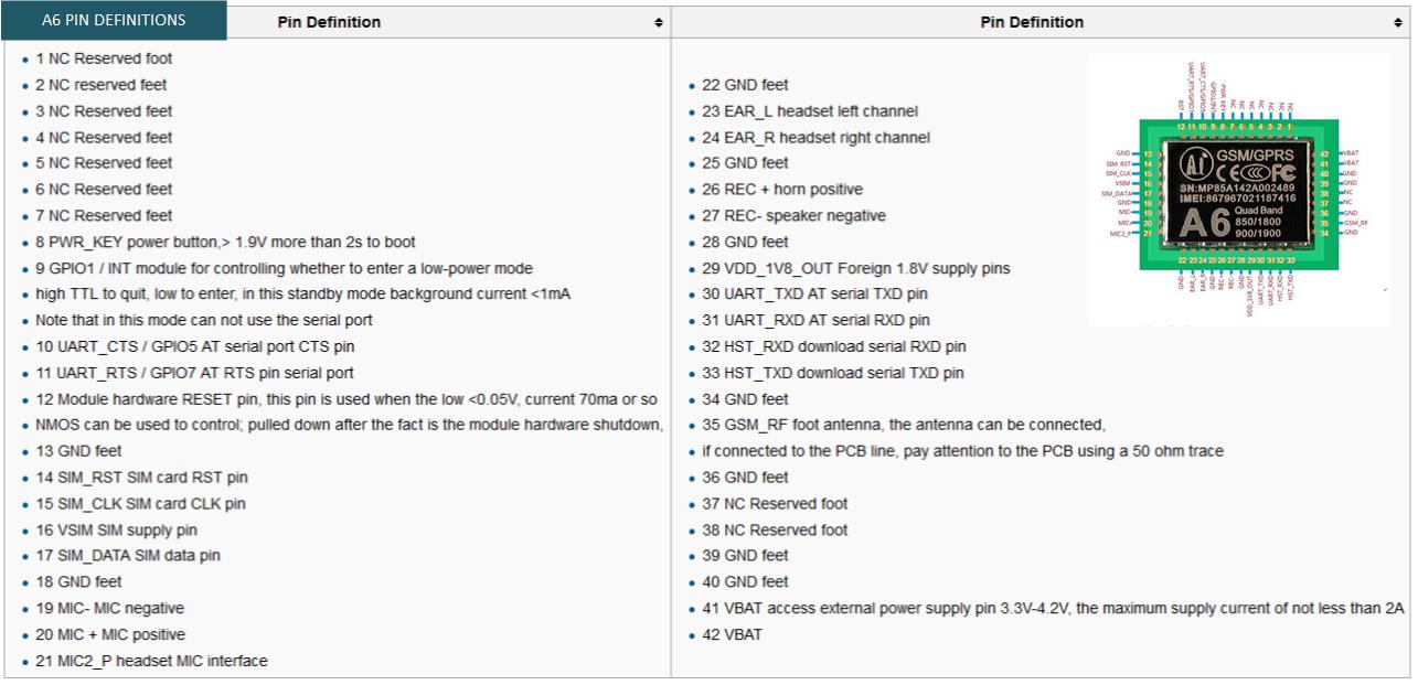
Pin-outs Definitions
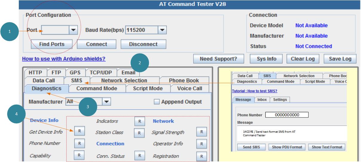
AT Command Tester
Working on AT – Command please see AT-Command documentation manual or you can use the AT-Command tester which can be downloaded below.
Test Sketch Code
|
1 2 3 4 5 6 7 8 9 10 11 12 13 14 15 16 17 18 19 20 21 22 23 24 25 26 27 28 29 30 31 32 33 34 35 36 37 38 39 40 41 42 43 44 45 46 47 48 49 50 51 52 53 54 55 56 57 58 59 60 61 62 63 64 65 66 67 68 69 70 71 72 73 74 75 76 77 78 79 80 81 82 83 84 85 86 87 88 89 90 91 92 93 94 95 96 97 98 99 100 101 102 103 104 105 106 107 108 109 110 111 112 113 114 115 116 117 118 119 120 121 122 123 124 125 126 127 128 129 130 131 132 133 134 135 136 137 138 139 140 141 142 143 144 145 146 147 148 149 150 151 152 153 154 155 156 157 158 159 160 161 162 163 164 165 166 167 168 169 170 171 172 173 174 175 176 177 178 179 180 181 182 183 184 185 186 187 188 189 190 191 192 193 194 195 196 197 198 199 200 201 202 203 204 205 206 207 208 209 210 211 212 213 214 215 216 217 218 219 220 221 222 223 224 225 226 227 228 229 230 231 232 233 234 235 236 237 238 239 240 241 242 243 244 245 246 247 248 249 250 251 252 253 254 255 256 257 258 259 260 261 262 263 264 265 266 267 268 269 270 271 272 273 274 275 276 277 278 279 280 281 282 283 284 285 286 |
#include <String.h> #define OK 1 #define NOTOK 2 #define TIMEOUT 3 #define RST 2 #define gsmboard Serial1 #ifndef gsmboard SoftwareSerial gsmboard (10, 3); #define abaudrate 9600 #else #define abaudrate 115200 #endif #define SERIALTIMEOUT 3000 char end_c[2]; void setup() { gsmboard.begin(abaudrate); // the GPRS baud rate Serial.begin(115200); // the GPRS baud rate // ctrlZ String definition end_c[0] = 0x1a; end_c[1] = '\0'; Serial.println("Start...."); pinMode(RST, OUTPUT); digitalWrite(RST, HIGH); delay(5000); digitalWrite(RST, LOW); delay(500); if (agsmbegin() != OK) { Serial.println("Error"); while (1 == 1); } } void loop() { //When startin up the code, you can use a terminal tools like puty, termcool, see the download option below, // Note: when you are in the terminal if your {t} w/o bracket you will execute the send text message command, // Note: when you type {d} w/o bracket you will execute the voice dial command. acommand("AT+CIPSTATUS", "OK", "yy", 10000, 2); Serial.println("Waiting for command"); if (Serial.available()) switch (Serial.read()) { case 't': Serial.println("Send SMS"); SendTextMessage(); break; case 'v': Serial.println("Make voice call"); DialVoiceCall(); break; case 'h': Serial.println("Not Available"); SubmitHttpRequest(); break; case 's': Serial.println("-----------------14CORE A7 A6C A20 TEST CODE ----------------------"); float batt = (float)analogRead(A0) * 5.165 / 594.0; sendSparkfunGSM(1, batt); break; } if ( gsmboard.available()) Serial.write( gsmboard.read()); delay(2000); } ///SendTextMessage() ///this function is to send a sms message void SendTextMessage() { acommand("AT+CMGF=1\r", "OK", "yy", 2000, 2); // Command to send SMS delay(100); acommand("AT+CMGS = \"+123123123\"", ">", "yy", 20000, 2); //Note: You need to add phone number delay(100); gsmboard.println("14CORE | GSM SMS TEST");//Your text message will be on this line gsmboard.println(end_c);//Control+Z in ASCII gsmboard.println(); } ///DialVoiceCall ///this function is to dial a voice call void DialVoiceCall() { acommand("AT+SNFS=0", "OK", "yy", 20000, 2); acommand("ATD+41615110889;", "OK", "yy", 20000, 2); //Command to dial a number } /* This is for HTTPREQUEST function to forward an http request note: delay is important to this function. */ void SubmitHttpRequest() { acommand("AT+CSQ", "OK", "yy", 20000, 2); acommand("AT+CGATT?", "OK", "yy", 20000, 2); acommand("AT+SAPBR=3,1,\"CONTYPE\",\"GPRS\"", "OK", "yy", 20000, 2); //Command for SAPBR, the to set connection type using gprs acommand("AT+CIPSTATUS", "OK", "yy", 10000, 2); acommand("AT+SAPBR=3,1,\"gprs.swisscom.ch\",\"\"", "OK", "yy", 20000, 2); //Command setting the APN, you need to fill in your local apn server acommand("AT+CIPSTATUS", "OK", "yy", 10000, 2); acommand("AT+SAPBR=1,1", "OK", "yy", 20000, 2); //setting the SAPBR, for detail you can refer to the AT command mamual gsmboard.println("AT+HTTPINIT"); //Command to initialize the HTTP request delay(2000); ShowSerialData(); gsmboard.println("AT+HTTPPARA=\"URL\",\"www.google.com.hk\"");// setting the httppara, the second parameter is the website you want to access delay(1000); ShowSerialData(); gsmboard.println("AT+HTTPACTION=0");//submit the request delay(10000);//the delay is very important, the delay time is base on the return from the website, if the return datas are very large, the time required longer. //while(!mySerial.available()); ShowSerialData(); gsmboard.println("AT+HTTPREAD");// read the data from the website you access delay(300); ShowSerialData(); gsmboard.println(""); delay(100); } bool sendSparkfunGSM(byte sparkfunType, float value1) { String host = "data.sparkfun.com"; // Test to push your data in sparkfun String publicKey = "your_public_key_will_here"; String privateKey = "your_private_key_will_here"; acommand("AT+CIPSTATUS", "OK", "yy", 10000, 2); acommand("AT+CGATT?", "OK", "yy", 20000, 2); acommand("AT+CGATT=1", "OK", "yy", 20000, 2); acommand("AT+CIPSTATUS", "OK", "yy", 10000, 2); acommand("AT+CGDCONT=1,\"IP\",\"gprs.swisscom.ch\"", "OK", "yy", 20000, 2); //bring up wireless connection acommand("AT+CIPSTATUS", "OK", "yy", 10000, 2); acommand("AT+CGACT=1,1", "OK", "yy", 10000, 2); acommand("AT+CIPSTATUS", "OK", "yy", 10000, 2); // acommand("AT+CIICR", "OK", "yy", 20000, 2); //pull up wireless connection // acommand("AT+CIPSTATUS", "OK", "yy", 10000, 2); acommand("AT+CIFSR", "OK", "yy", 20000, 2); //Command to get your local IP address acommand("AT+CIPSTATUS", "OK", "yy", 10000, 2); acommand("AT+CIPSTART=\"TCP\",\"" + host + "\",80", "CONNECT OK", "yy", 25000, 2); //start up the connection // ainput(); acommand("AT+CIPSTATUS", "OK", "yy", 10000, 2); acommand("AT+CIPSEND", ">", "yy", 10000, 1); //Command start sending data to a remote server delay(500); gsmboard.print("GET /input/"); gsmboard.print(publicKey); gsmboard.print("?private_key="); gsmboard.print(privateKey); gsmboard.print("&battery="); gsmboard.print(value1, 2); gsmboard.print(" HTTP/1.1"); gsmboard.print("\r\n"); gsmboard.print("HOST: "); gsmboard.print(host); gsmboard.print("\r\n"); gsmboard.print("\r\n"); Serial.print("GET /input/"); Serial.print(publicKey); Serial.print("?private_key="); Serial.print(privateKey); Serial.print("&battery="); Serial.print(value1, 2); Serial.print(" HTTP/1.1"); Serial.print("\r\n"); Serial.print("HOST: "); Serial.print(host); Serial.print("\r\n"); Serial.print("\r\n"); acommand(end_c, "HTTP/1.1", "yy", 30000, 1); //Start send data to remote server unsigned long entry = millis(); //gsmboard.println(end_c); //sending ctrlZ acommand("AT+CIPSTATUS", "OK", "yy", 10000, 2); acommand("AT+CIPCLOSE", "OK", "yy", 15000, 1); acommand("AT+CIPSTATUS", "OK", "yy", 10000, 2); delay(100); Serial.println("Done......................"); } byte await(String response1, String response2, int timeOut) { unsigned long entry = millis(); int count = 0; String reply = agsmread(); byte retVal = 99; do { reply = agsmread(); if (reply != "") { Serial.print((millis() - entry)); Serial.print(" ms "); Serial.println(reply); } } while ((reply.indexOf(response1) + reply.indexOf(response2) == -2) && millis() - entry < timeOut ); if ((millis() - entry) >= timeOut) { retVal = TIMEOUT; } else { if (reply.indexOf(response1) + reply.indexOf(response2) > -2) retVal = OK; else retVal = NOTOK; } // Serial.print("retVal = "); // Serial.println(retVal); return retVal; } byte acommand(String command, String response1, String response2, int timeOut, int repetitions) { byte returnValue = NOTOK; byte count = 0; while (count < repetitions && returnValue != OK) { gsmboard.println(command); Serial.print("Command: "); Serial.println(command); if (await(response1, response2, timeOut) == OK) { // Serial.println("OK"); returnValue = OK; } else returnValue = NOTOK; count++; } return returnValue; } void ainput() { String thisString; char buffer[100]; while (1 == 1) { if (Serial.available()) { thisString = Serial.readStringUntil('\n'); thisString.toCharArray(buffer, thisString.length() + 1); if (thisString.indexOf("end") == 0) { gsmboard.write(end_c); Serial.println("end"); } else { gsmboard.write(buffer); gsmboard.write('\n'); } } if (gsmboard.available()) { Serial.write(gsmboard.read()); } } } bool agsmbegin() { gsmboard.println("AT+CREG?"); byte hi = await("1,", "5,", 1500); // 1: registered, home network ; 5: registered, roaming while ( hi != OK) { gsmboard.println("AT+CREG?"); hi = await("1,", "5,", 1500); } if (acommand("AT&F0", "OK", "yy", 5000, 2) == OK) { // To reset as factory settings if (acommand("ATE0", "OK", "yy", 5000, 2) == OK) { // to disable the Echo if (acommand("AT+CMEE=2", "OK", "yy", 5000, 2) == OK) return OK; // Activate better error messages else return NOTOK; } } } void ShowSerialData() { unsigned long entry = millis(); while ( gsmboard.available() != 0 && millis() - entry < SERIALTIMEOUT) Serial.println(gsmboard.readStringUntil('\n')); } String agsmread() { String reply = ""; if (gsmboard.available()) { reply = gsmboard.readString(); } // Serial.print("Reply : "); // Serial.println(reply); return reply; } |
Downloads
- GSM AT Command Error Code List | FILE
- Download AT-Command Datasheet Manual for A7 – A6 – A6C | PDF 1 | PDF 2
- Download AT-Command Datasheet Manual for A20 | PDF
- Download A7 Breakout Schematics Diagram | LINK
- Download A6C Breakout Schematics Diagram| LINK
- Download A6 Breakout Schematics Diagram | LINK
- Download A20 Breakout Schematics Diagram | PDF
- Download Serial Tools | RealTerm | Putty | CoolTerm | TeraTerm
- Download AT Command Test Tool > http://m2msupport.net/m2msupport/download-at-command-tester/


Hello, can some one help me
I have A6 GPRS Module Development Board GSM.
Can I connect to the A6, a motion detector and a microphone?
The motion detector is to activate an SMS to my phone.
The microphone is for me to call the A6 and hear the sound.
It’s possible?
Thanks