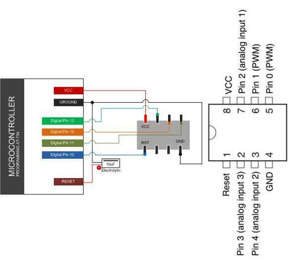
This guide we will going to burn / program the chip along with the Arduino IDE and hardware board, ATtine 25, 45 and 85 is a low power CMOS 8bit microcontroller base on the AVR enhanced RISC architecture by executing powerful instructions in a single clock cycle, the ATtiny 25, 45, and 85 achieves throughputs approaching 1 MIPS per Mhz allowing the system designer to optimize the power consumption versus processing speed.
Wiring the ATtiny with Arduino Board
Arduino UNO with ATTINY Integration
- AT Pin 8 > MCU +5v
- AT Pin 4 > MCU GND
- AT Pin 1 > MCU Digital Pin 10
- AT Pin 5 > MCU Digital Pin 11
- AT Pin 6 > MCU Digital Pin 12
- AT Pin 7 > MCU Digital Pin 13
- Place a 10uf capacitor Arduino MCU GND to MCU RST(Reset)
Programming The ATTINY
Download the ATtiny ChipBurner.zip located below, then unzip the zip file should contain AT-chip-burner folder at that folder you see another folder burn-atty, Open your Arduino IDE locate your sketchbook folder you will see the location the preference dialog in the Arduino IDE software.
Create a new sub-folder called ChipBurner in the skethbook folder, copy the burn-atty folder not the AT-Chip-Burner folder from the unzipped. you should see folder structure Documets / Arduino / ChipBurner / burn-atty that contains the text file boards.txt and another folder called variants. Restart you Arduino IDE you should see ATiny Entries in the tools > Arduino Board Menu
Programming Instruction for ATTiny
We we’re going to use the Arduino as an ISP to upload our code to ATTiny Chip. Open the Blink sketch from Arduino IDE Example Program, then change the pin number from 13 to 0. Select the right item from the..
TOOLS > MENU BOARD ( Serial Port Set to the Master Arduino Board)
Select appropriate item from the..
TOOLS > PROGRAMMER MENU ( Example Arduino as ISP) if your using you Arduino board as ISP programmer. Then select USBtinyISP for the USBTinyISP, FabISP or TinyProgrammer etc. UPLOAD your Sketch to ATTiny.
You will see “Done Uploading” you can see that below status windows on the Arduino IDE. Then if your going to connect the LED between Pin 0 and Ground you shoul see the LED will blink on and off.
You should see “Done uploading.” in the Arduino software and no error messages. If you then connect an LED between pin 0 and ground, you should see the LED is blinking on and off. Note that you may need to disconnect the LED before uploading a new program.
Download the ATTiny Chip Programmer Here | ZIP
Download the ATTiny 24 44 84 Datasheet Here | PDF
Download the ATTiny 25 45 85 Datasheet Here | PDF


