Where going demonstrate how to use the DS1302 Real Time Clock with Arduino board, the DS1302 trickle-charge timekeeping chip contains a real-time clock and calendar and 31bytes of static RAM and its communicating with a microcontroller or microprocessor via a simple serial interface. The DS1302 real time clock and calendar provides seconds, minutes, hours, day, date, month, and a year information, end of the month date is automatically adjusted for months with fewer than 31 days, including corrections for leap year. The clock operates in 24 hours or 12 hours format with AM and PM indicator.
This module is very useful for making things running on date and time, it can be interface to any micro controller or micro processor in order to control the events. this also helpful specially when driving timings and execution on a precise time.
Interfacing the DS1302 with a MCU is simplified by using SSC(Synchronous Serial Communication) Only three wires are required to communicate with the DS1302 clock Random Access Memory or RAM. The required wire will be CE(Chip Enable), IO(Input Output Data Line), and SCLK (Serial Clock). from the clock RAM has a 1 byte at a time or in a burst of up to 31 bytes and data can be transferred also. These chip is designed to operate on very low power and retain data and clock information on less than 1uW.
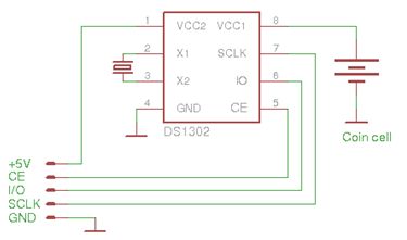
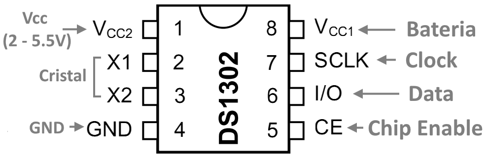
The wiring schematics diagram above for the DS1302 Clock Module, can support two power supply Voltage input 1 and Voltage Input 2, Voltage is set to the primary the chip can handle typically 3.3v ~ 5v, the voltage input 2 also is set to accept the primary power. The VCC 1 is set for the backup power, provided by 3.3v Coin Battery. The quarts crystal is placed between the pin 2 and pin 3, the pin 5 and 7 are assigned for the data communication between the module and the microcontroller. The module also can handle Pulse With Modulation, Digital, Communication or Analog pins and work well.
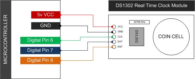
Wiring to Arduino Board
Before you can run the code below you need to include the code library witch is can be found here | Zip
|
1 2 3 4 5 6 7 8 9 10 11 12 13 14 15 16 17 18 19 20 21 22 23 24 25 26 27 28 29 30 31 32 33 34 |
#include <MyRealTimeClock.h> MyRealTimeClock myRTC(6, 7, 8); // Assign Digital Pins void setup() { Serial.begin(9600); /* To set the current time and date in specific format | Second 00 | Minute 59 | Hour 10 | Day 12 | Month 07 | Year 2015 | */ myRTC.setDS1302Time(00, 59, 10, 12 , 10, 07, 2015); } void loop() { // Allow the update of variables for time / accessing the individual element. myRTC.updateTime(); Serial.print("Current Date / Time: "); Serial.print(myRTC.dayofmonth); // Element 1 Serial.print("/"); Serial.print(myRTC.month); // Element 2 Serial.print("/"); Serial.print(myRTC.year); // Element 3 Serial.print(" "); Serial.print(myRTC.hours); // Element 4 Serial.print(":"); Serial.print(myRTC.minutes); // Element 5 Serial.print(":"); Serial.println(myRTC.seconds); // Element 6 delay( 5000); } |
Download The Code Library Here | Zip
Download The Sample Demo Code 1 Here | Zip
Download The Sample Demo Code 2 Here | Zip
Download The Data Sheet Here | PDF
Useful Link from the Official Site | http://playground.arduino.cc/Main/DS1302


finally i do that thanks u….
Hello i load the program but i not working properly minutes increase randomly and its shown 63 min. which is not possible. So give please approximate solution
How to set time manually using push buttons?
There is a bug in the library. The month is supposed to be written in octal and the highest value is 07 (July).
noted! i dig to the library..