RS-485 is a versatile serial communication standard that enables reliable data transmission over long distances (up to 1,200 meters) and in electrically noisy environments. Unlike common protocols like UART (which uses TX/RX pins), RS-485 operates on a differential signaling method, transmitting data over two wires (A and B) to cancel out noise and ensure signal integrity.
Why Use RS-485 with Arduino?
- Long-Distance Communication: Ideal for industrial sensors, agricultural monitoring, or building automation.
- Noise Immunity: Performs well in environments with motors, power lines, or interference.
- Multi-Device Networks: Supports up to 32 devices on a single bus (expandable with repeaters).
MAX485 IC is a popular RS-485 transceiver that converts Arduino’s UART signals to RS-485.
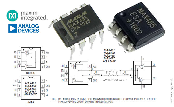
The MAX485 is a low-power transceiver IC from Maxim Integrated designed for RS-485 and RS-422 communication, enabling robust differential data transmission over long distances (up to 1,200 meters) with noise immunity, making it ideal for industrial automation, MODBUS networks, and embedded systems.
Features :
- Half-duplex operation (transmit or receive at a time)✔️
- 5V supply voltage with low power consumption for battery-powered applications✔️
- High-speed data rates up to 2.5 Mbps.✔️
- Differential signaling to reject noise and extend cable runs✔️
- Multi-device support (up to 32 nodes on a single bus)✔️
REQUIREMENTS:
- Arduino IDE | PlatformIO | Visual Studio Code
- ARDUINO BOARDS & OTHER COMPATIBLE BOARDS
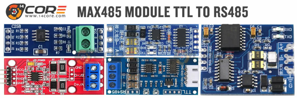
- MAX485 MODULE
For our testing propose environment, we will utilize the MAX485 RS-485 transceiver module due to its exceptional prototyping efficiency and robust communication capabilities. This module provides an optimal balance of performance and convenience, making it particularly well-suited for rapid development cycles and experimental setups.
Key advantages for lab use include:
- Plug-and-play functionality with standard 0.1″ pin headers for seamless integration with breadboards and prototype PCBs✔️
- Screw terminal options for secure long-distance wiring during signal integrity testing✔️
- 5V logic compatibility that interfaces directly with common lab equipment like Arduino, Raspberry Pi, and PIC microcontrollers✔️
- Built-in fail-safe features (thermal shutdown, short-circuit protection) that prevent damage during prototype debugging✔️
- Modular design that supports quick replacement or reconfiguration between experiments✔️
The module’s differential signaling proves invaluable in lab settings where electrical noise from nearby equipment can distort measurements, while its support for multi-drop networks (up to 32 devices) allows scalable testing of distributed sensor systems. For time-sensitive projects, the 2.5 Mbps maximum data rate enables high-speed data logging without compromising the 1,200-meter range – particularly useful when validating long-haul communication in industrial automation scenarios.
We specifically selected this implementation over raw IC solutions because the module format:
- Eliminates the need for external termination resistor calculations✔️
- Provides LED indicators for visual communication status checks✔️
- Includes essential protection circuits not always present in bare IC designs✔️
This combination of reliability, diagnostic features, and prototyping convenience makes the MAX485 module an indispensable tool for both preliminary research and rigorous validation phases in our laboratory workflow.
SOURCE CODE FOR TX-TRANSMIT
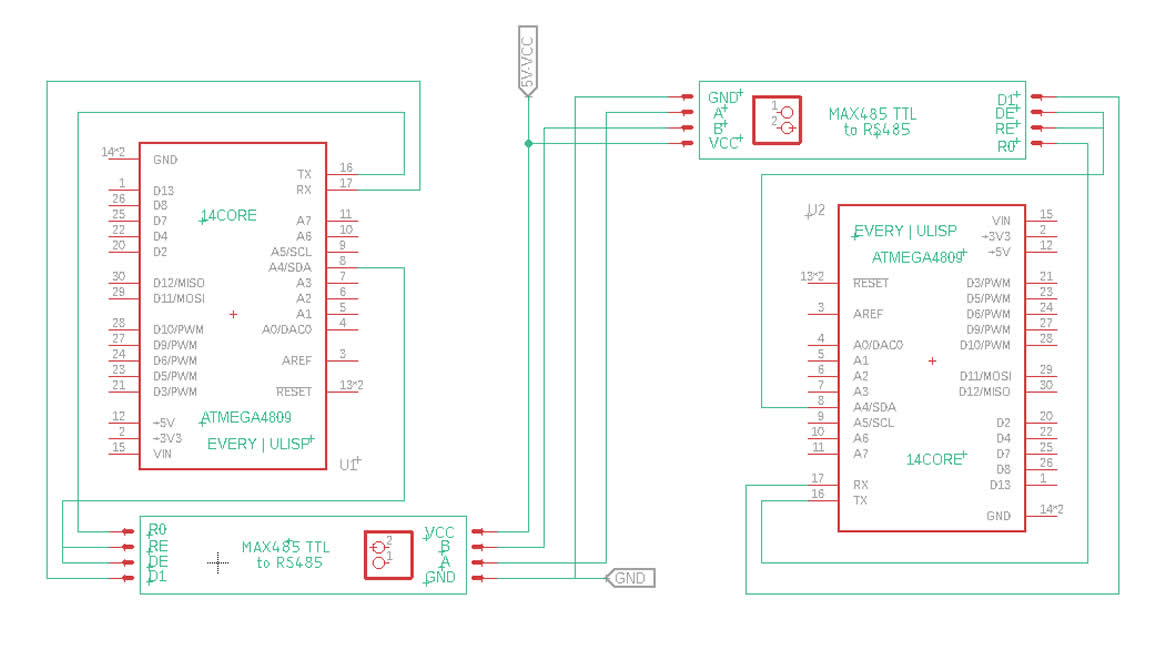
Communication Process: The Arduino Nano (or equivalent) begins in transmit mode while a second Arduino Nano (or equivalent device) starts in receive mode. The primary Nano sends the character ‘9’ through its serial interface before switching to receive mode. When the secondary device receives this character, it verifies if it matches ‘9’ and responds by sending back the identification string “AcruxTekIsld” if valid. Meanwhile, the secondary device continuously toggles an LED connected to pin 13 every two seconds as a system heartbeat indicator. The primary Nano then receives this response string and displays it on the serial monitor.
Technical Implementation Notes: The Serial.readString() function doesn’t work reliably in this RS-485 communication because the serial buffer fails to receive proper termination characters due to uncalibrated biasing and terminating resistors that don’t match the cable impedance. Instead, the solution uses a while loop (while(Serial1.available() && getdata!=’d’)) to read data character-by-character until it encounters the ‘d’ terminator. This approach proves necessary because unlike RS-232 communications – where Serial.readString() works perfectly due to proper signal termination and defined voltage levels – RS-485 requires more careful buffer handling.
Additional Recommendations: For more robust communication, consider adding 120Ω termination resistors at both ends, implementing software timeouts for error handling, and including checksum verification. The onboard LED on pin 13 serves multiple diagnostic purposes: confirming power status, verifying program execution continuity, and providing a visual timing reference. For debugging, helpful practices include inserting status messages at mode transitions, monitoring the control pin state with an oscilloscope, and ensuring consistent baud rates between devices.
|
1 2 3 4 5 6 7 8 9 10 11 12 13 14 15 16 17 18 19 20 21 22 23 24 25 26 27 28 29 30 31 32 33 34 35 36 37 38 39 40 41 42 43 44 45 46 47 48 49 50 |
/* * 14CORE - TEST CODE * RS-485 Communication Test Sketch * Uses MAX485 module with DE/RE control for half-duplex communication * Sends a request and listens for response from another device (e.g., Arduino Pro Mini) */ // Pin Definitions #define RS485_CONTROL_PIN 8 // DE/RE control pin for MAX485 module // HIGH = Transmit mode, LOW = Receive mode void setup() { // Initialize serial ports: Serial1.begin(9600); // Hardware Serial1 for RS-485 communication Serial.begin(9600); // USB Serial for debugging/monitoring // Configure RS-485 control pin pinMode(RS485_CONTROL_PIN, OUTPUT); digitalWrite(RS485_CONTROL_PIN, LOW); // Start in Receive mode by default Serial.println("RS-485 Communication Test Initialized"); } void loop() { char receivedChar = 'm'; // Initialize with dummy value char requestChar = '9'; // Character to send as request // --- TRANSMISSION PHASE --- digitalWrite(RS485_CONTROL_PIN, HIGH); // Enable Transmit mode Serial1.print(requestChar); // Send request character // Note: Small delay may be needed here for transmission to complete digitalWrite(RS485_CONTROL_PIN, LOW); // Return to Receive mode delay(1000); // Wait for response (adjust based on device response time) // --- RECEPTION PHASE --- if(Serial1.available()) { // Check if data is available Serial.print("Received: "); // Read all available data until terminator 'd' is found while(Serial1.available() && receivedChar != 'd') { receivedChar = Serial1.read(); // Read incoming byte Serial.print(receivedChar); // Echo to Serial Monitor } Serial.println(); // New line after complete message } // Note: Consider adding error handling for timeout cases } |
SOURCE CODE FOR RX-RECEIVE
|
1 2 3 4 5 6 7 8 9 10 11 12 13 14 15 16 17 18 19 20 21 22 23 24 25 26 27 28 29 30 31 32 33 34 35 36 37 38 39 40 41 42 43 44 45 |
/* 14CORE - TEST CODE * RS-485 Communication Slave Device * Arduino Nano (or equivalent) responding to master requests * - Listens for character '9' on serial * - Responds with identification string when triggered * - Includes heartbeat LED indicator */ void setup() { // Initialize serial communication: // Serial1.begin(9600); // Uncomment for Arduino Leonardo (uses Serial1) Serial.begin(9600); // Initialize primary serial port (USB on Nano) // while(!Serial1); // Uncomment for Arduino Leonardo (wait for serial) // Configure output pins: pinMode(13, OUTPUT); // Onboard LED (heartbeat indicator) pinMode(8, OUTPUT); // DE/RE control pin for MAX485 module // LOW = Receive mode, HIGH = Transmit mode } void loop() { char receivedChar = 'c'; // Initialize with default character // Start each cycle with LED off and in receive mode digitalWrite(13, LOW); // Turn LED off digitalWrite(8, LOW); // Set RS-485 to receive mode // Check for incoming serial data if(Serial.available()) { receivedChar = Serial.read(); // Read the incoming byte } // If we received the trigger character '9' if(receivedChar == '9') { digitalWrite(8, HIGH); // Switch to transmit mode // Send identification string (split for readability) Serial.print("14CORE - TEST CODE"); // First part of identifier Serial.print("Isld"); // Second part of identifier // Note: Transmit mode will switch back to receive on next loop } // Heartbeat LED blinking pattern (2 seconds ON, 2 seconds OFF) delay(2000); // Maintain LED off state for 2s digitalWrite(13, HIGH); // Turn LED on delay(2000); // Maintain LED on state for 2s |


