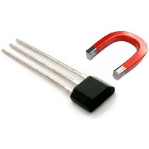
In these illustration we will going to wire the Hall-Effect Switch in our Arduino board. Hall-effect switch are monolithic integrated circuit with tither magnetic specification, designed to operate continuously over temperature +150 degree Celsius and are more stable with both temperature and supply voltage changes. The unipolar switching characteristic makes these devices ideal for use with a simple bar or rod magnet. The four basic device are 3141, 3142, 3143 and the 3144 are identical except for magnetic switch points.

Required Components
1x Arduino UNO/MEGA/NANO/PRO
1x Hall Effect Switch Module
1x 220 Ohms Resistor
Solder Less Bread Board
Jumper Wires
Wiring Diagram
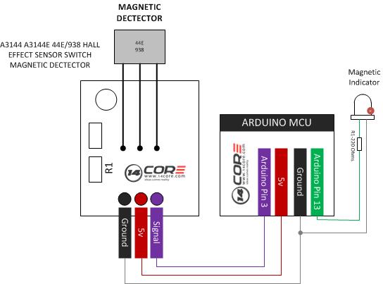
In this illustration we wire the LED to pin 13 as our output, and our Hall Magnetic Sensor it is connected to the Arduino Digital Pin 3, if the sensor detect a magnetic field it will turn the LED to HIGH,
Arduino Sketch
|
1 2 3 4 5 6 7 8 9 10 11 12 13 14 15 16 17 18 19 20 21 22 23 24 25 |
/* 14CORE Magnetic Sensor Demo */ int MYLED=13; int MAGNETICMAGNETICSENSOR=3; int val; void setup() { pinMode(MYLED,OUTPUT); pinMode MAGNETICSENSOR,INPUT); } void loop() { val=digitalRead(MAGNETICSENSOR); if(val==HIGH) { digitalWrite(MYLED, HIGH); } Else { digitalWrite(MYLED, LOW); } } |
Download the 44E938 Hall Effect Datasheet Here | PDF


