The MPU 6050 sensor board contains a MEMS ACCELEROMETER and MEMS GYRO a single chip that provide a very accurate data, as it contains 16bits analog to digital conversion hardware for each channel that captures the X, Y, and Z channel at the same time. The board sensor uses i2c Bus interface that you can just hookup to the microcontroller specially while working in Arduino board.
The MPU 6050 combines both an accelerometer and a gyro together in one single chip. There two type of MPU version there is 6050 and 9150 that has a MAGNETOMETER (Compass) integrate to chip. On this illustration we will cover only the MPU 6050 without using the magnetometer.
Getting the raw values for the accelerometer and the gyro is quite easy. The sleep mode has to be disable and then the registers for the accelerometer and gyro can be read. The sensor also contains 1025 bytes FIFO buffer that can be programmed to be place into FIFO buffer and the buffer can be ready by the microcontroller.
The FIFO buffer is used together with the interrupt signal if the MPU 6050 places a data into the FIFO buffer it send signals to the microcontroller with the interrupt signal. The microcontroller knows that there is a data coming from FIFO buffer that ready to be read.
The MPU 6050 always acts as a slave to the Arduino with the SDA and SCL pins connected to i2c BUS. The board has also its own i2c controller to be a master on a second sub i2c bus. It uses the pins AUX_DA and AUX_CL for the second sub i2c BUS you can control the magnetometer and the values of the magnetometer can be passed into the microcontroller.

The sensor has a Digital Motion Processor (DMP) or Digital Motion Processing Unit these DMP can be programmed with firmware and can do a complex calculation with the sensor values.
The Digital Motion Processor can calculate directly to the chip at this state the load reduce for the microcontroller. The DMP can even do a calculations with the sensor values of another chip, for example if the magnetometer connected to the second i2c Bus.
Using Multiple Sensor
At the MPU6050 board Pin ADO select between i2C address 0x68 and 0x69 that makes it possible to have two of these sensors in a project most breakout boards have a pullup or pulldown resistor to make ADO default LOW or HIGH, you just need to connect the ADO to GND or 3.3v for the other i2C address.
Wiring one or more board MPU6050 are needed to implement this project the i2C bus can be extended with CD74HC4067 De-multiplexer breakout board.
Wiring Diagram with Arduino

MPU 6050 Code
|
1 2 3 4 5 6 7 8 9 10 11 12 13 14 15 16 17 18 19 20 21 22 23 24 25 26 27 28 29 30 31 32 33 34 35 36 37 38 39 40 41 42 43 44 45 46 47 48 49 50 51 52 53 54 55 56 57 58 59 60 61 62 63 64 65 66 67 68 69 70 71 72 73 74 75 76 77 78 79 80 81 82 83 84 85 86 87 88 89 90 91 92 93 94 95 96 97 98 99 100 101 102 103 104 105 106 107 108 109 110 111 112 113 114 115 116 117 118 119 120 121 122 123 124 125 126 127 128 129 130 131 132 133 134 135 136 137 138 139 140 141 142 143 144 145 146 147 148 149 150 151 152 153 154 155 156 157 158 159 160 161 162 163 164 165 166 167 168 169 170 171 172 173 174 175 176 177 178 179 180 181 182 183 184 185 186 187 188 189 190 191 192 193 194 195 196 197 198 199 200 201 202 203 204 205 206 207 208 209 210 211 212 213 214 215 216 217 218 219 220 221 222 223 224 225 226 227 228 229 230 231 232 233 234 235 236 237 238 239 240 241 242 243 244 245 246 247 248 249 250 251 252 253 254 255 256 257 258 259 260 261 262 263 264 265 266 267 268 269 270 271 272 273 274 275 276 277 278 279 280 281 282 283 284 285 286 287 288 289 290 291 292 293 294 295 296 297 298 299 300 301 302 303 304 305 306 307 308 309 310 311 312 313 314 315 316 317 318 319 320 321 322 323 324 325 326 327 328 329 330 331 332 333 334 335 336 337 338 339 340 341 342 343 344 345 346 347 348 349 350 351 352 353 354 355 356 357 358 359 360 361 362 363 364 365 366 367 368 369 370 371 372 373 374 375 376 377 378 379 380 381 382 383 384 385 386 387 388 389 390 391 392 393 394 395 396 397 398 399 400 401 402 403 404 405 406 407 408 409 410 411 412 413 414 415 416 417 418 419 420 421 422 423 424 425 426 427 428 429 430 431 432 433 434 435 436 437 438 439 440 441 442 443 444 445 446 447 448 449 450 451 452 453 454 455 456 457 458 459 460 461 462 463 464 465 466 467 468 469 470 471 472 473 474 475 476 477 478 479 480 481 482 483 484 485 486 487 488 489 490 491 492 493 494 495 496 497 498 499 500 501 502 503 504 505 506 507 508 509 510 511 512 513 514 515 516 517 518 519 520 521 522 523 524 525 526 527 528 529 530 531 532 533 534 535 536 537 538 539 540 541 542 543 544 545 546 547 548 549 550 551 552 553 554 555 556 557 558 559 560 561 562 563 564 565 566 567 568 569 570 571 572 573 574 575 576 577 578 579 580 581 582 583 584 585 586 587 588 589 590 591 592 593 594 595 596 597 598 599 600 601 602 603 604 605 606 607 608 609 610 611 612 613 614 615 616 617 618 619 620 621 622 623 624 625 626 627 628 629 630 631 632 633 634 635 636 637 638 639 640 641 642 643 644 645 646 647 648 649 650 651 652 653 654 655 656 657 658 659 660 661 662 663 664 665 666 667 668 669 670 671 672 673 674 675 676 677 678 679 680 681 682 683 684 685 686 687 688 689 690 691 692 693 694 695 696 697 698 699 700 701 702 703 704 705 706 707 708 709 710 711 712 713 714 715 716 717 718 719 720 721 722 723 724 725 726 727 728 729 730 731 732 733 734 735 736 737 738 739 740 741 742 743 744 745 746 747 748 749 750 751 752 753 754 755 756 757 758 759 760 761 762 763 764 765 766 767 768 769 770 771 772 773 774 775 776 777 778 779 780 781 782 783 784 785 786 787 788 789 790 791 792 793 794 795 796 797 798 799 800 801 802 803 804 805 806 807 808 809 810 811 812 813 814 815 816 817 818 819 820 821 822 823 824 825 826 827 828 829 830 831 832 833 834 835 836 837 838 839 840 841 842 843 844 845 846 847 848 849 850 851 852 853 854 855 856 857 858 859 860 861 862 863 864 865 866 867 868 869 870 871 872 873 874 875 876 877 878 879 880 881 882 883 884 |
// MPU-6050 Accelerometer + Gyro // ----------------------------- // // By arduino.cc // // June 2012 // first version // July 2013 // The 'int' in the union for the x,y,z // changed into int16_t to be compatible // with Arduino Due. // // Open Source / Public Domain // // Using Arduino 1.0.1 // It will not work with an older version, // since Wire.endTransmission() uses a parameter // to hold or release the I2C bus. // // Documentation: // - The InvenSense documents: // - "MPU-6000 and MPU-6050 Product Specification", // PS-MPU-6000A.pdf // - "MPU-6000 and MPU-6050 Register Map and Descriptions", // RM-MPU-6000A.pdf or RS-MPU-6000A.pdf // - "MPU-6000/MPU-6050 9-Axis Evaluation Board User Guide" // AN-MPU-6000EVB.pdf // // The accuracy is 16-bits. // // Temperature sensor from -40 to +85 degrees Celsius // 340 per degrees, -512 at 35 degrees. // // At power-up, all registers are zero, except these two: // Register 0x6B (PWR_MGMT_2) = 0x40 (I read zero). // Register 0x75 (WHO_AM_I) = 0x68. // #include <Wire.h> // The name of the sensor is "MPU-6050". // For program code, I omit the '-', // therefor I use the name "MPU6050....". // Register names according to the datasheet. // According to the InvenSense document // "MPU-6000 and MPU-6050 Register Map // and Descriptions Revision 3.2", there are no registers // at 0x02 ... 0x18, but according other information // the registers in that unknown area are for gain // and offsets. // #define MPU6050_AUX_VDDIO 0x01 // R/W #define MPU6050_SMPLRT_DIV 0x19 // R/W #define MPU6050_CONFIG 0x1A // R/W #define MPU6050_GYRO_CONFIG 0x1B // R/W #define MPU6050_ACCEL_CONFIG 0x1C // R/W #define MPU6050_FF_THR 0x1D // R/W #define MPU6050_FF_DUR 0x1E // R/W #define MPU6050_MOT_THR 0x1F // R/W #define MPU6050_MOT_DUR 0x20 // R/W #define MPU6050_ZRMOT_THR 0x21 // R/W #define MPU6050_ZRMOT_DUR 0x22 // R/W #define MPU6050_FIFO_EN 0x23 // R/W #define MPU6050_I2C_MST_CTRL 0x24 // R/W #define MPU6050_I2C_SLV0_ADDR 0x25 // R/W #define MPU6050_I2C_SLV0_REG 0x26 // R/W #define MPU6050_I2C_SLV0_CTRL 0x27 // R/W #define MPU6050_I2C_SLV1_ADDR 0x28 // R/W #define MPU6050_I2C_SLV1_REG 0x29 // R/W #define MPU6050_I2C_SLV1_CTRL 0x2A // R/W #define MPU6050_I2C_SLV2_ADDR 0x2B // R/W #define MPU6050_I2C_SLV2_REG 0x2C // R/W #define MPU6050_I2C_SLV2_CTRL 0x2D // R/W #define MPU6050_I2C_SLV3_ADDR 0x2E // R/W #define MPU6050_I2C_SLV3_REG 0x2F // R/W #define MPU6050_I2C_SLV3_CTRL 0x30 // R/W #define MPU6050_I2C_SLV4_ADDR 0x31 // R/W #define MPU6050_I2C_SLV4_REG 0x32 // R/W #define MPU6050_I2C_SLV4_DO 0x33 // R/W #define MPU6050_I2C_SLV4_CTRL 0x34 // R/W #define MPU6050_I2C_SLV4_DI 0x35 // R #define MPU6050_I2C_MST_STATUS 0x36 // R #define MPU6050_INT_PIN_CFG 0x37 // R/W #define MPU6050_INT_ENABLE 0x38 // R/W #define MPU6050_INT_STATUS 0x3A // R #define MPU6050_ACCEL_XOUT_H 0x3B // R #define MPU6050_ACCEL_XOUT_L 0x3C // R #define MPU6050_ACCEL_YOUT_H 0x3D // R #define MPU6050_ACCEL_YOUT_L 0x3E // R #define MPU6050_ACCEL_ZOUT_H 0x3F // R #define MPU6050_ACCEL_ZOUT_L 0x40 // R #define MPU6050_TEMP_OUT_H 0x41 // R #define MPU6050_TEMP_OUT_L 0x42 // R #define MPU6050_GYRO_XOUT_H 0x43 // R #define MPU6050_GYRO_XOUT_L 0x44 // R #define MPU6050_GYRO_YOUT_H 0x45 // R #define MPU6050_GYRO_YOUT_L 0x46 // R #define MPU6050_GYRO_ZOUT_H 0x47 // R #define MPU6050_GYRO_ZOUT_L 0x48 // R #define MPU6050_EXT_SENS_DATA_00 0x49 // R #define MPU6050_EXT_SENS_DATA_01 0x4A // R #define MPU6050_EXT_SENS_DATA_02 0x4B // R #define MPU6050_EXT_SENS_DATA_03 0x4C // R #define MPU6050_EXT_SENS_DATA_04 0x4D // R #define MPU6050_EXT_SENS_DATA_05 0x4E // R #define MPU6050_EXT_SENS_DATA_06 0x4F // R #define MPU6050_EXT_SENS_DATA_07 0x50 // R #define MPU6050_EXT_SENS_DATA_08 0x51 // R #define MPU6050_EXT_SENS_DATA_09 0x52 // R #define MPU6050_EXT_SENS_DATA_10 0x53 // R #define MPU6050_EXT_SENS_DATA_11 0x54 // R #define MPU6050_EXT_SENS_DATA_12 0x55 // R #define MPU6050_EXT_SENS_DATA_13 0x56 // R #define MPU6050_EXT_SENS_DATA_14 0x57 // R #define MPU6050_EXT_SENS_DATA_15 0x58 // R #define MPU6050_EXT_SENS_DATA_16 0x59 // R #define MPU6050_EXT_SENS_DATA_17 0x5A // R #define MPU6050_EXT_SENS_DATA_18 0x5B // R #define MPU6050_EXT_SENS_DATA_19 0x5C // R #define MPU6050_EXT_SENS_DATA_20 0x5D // R #define MPU6050_EXT_SENS_DATA_21 0x5E // R #define MPU6050_EXT_SENS_DATA_22 0x5F // R #define MPU6050_EXT_SENS_DATA_23 0x60 // R #define MPU6050_MOT_DETECT_STATUS 0x61 // R #define MPU6050_I2C_SLV0_DO 0x63 // R/W #define MPU6050_I2C_SLV1_DO 0x64 // R/W #define MPU6050_I2C_SLV2_DO 0x65 // R/W #define MPU6050_I2C_SLV3_DO 0x66 // R/W #define MPU6050_I2C_MST_DELAY_CTRL 0x67 // R/W #define MPU6050_SIGNAL_PATH_RESET 0x68 // R/W #define MPU6050_MOT_DETECT_CTRL 0x69 // R/W #define MPU6050_USER_CTRL 0x6A // R/W #define MPU6050_PWR_MGMT_1 0x6B // R/W #define MPU6050_PWR_MGMT_2 0x6C // R/W #define MPU6050_FIFO_COUNTH 0x72 // R/W #define MPU6050_FIFO_COUNTL 0x73 // R/W #define MPU6050_FIFO_R_W 0x74 // R/W #define MPU6050_WHO_AM_I 0x75 // R // Defines for the bits, to be able to change // between bit number and binary definition. // By using the bit number, programming the sensor // is like programming the AVR microcontroller. // But instead of using "(1<<X)", or "_BV(X)", // the Arduino "bit(X)" is used. #define MPU6050_D0 0 #define MPU6050_D1 1 #define MPU6050_D2 2 #define MPU6050_D3 3 #define MPU6050_D4 4 #define MPU6050_D5 5 #define MPU6050_D6 6 #define MPU6050_D7 7 // AUX_VDDIO Register #define MPU6050_AUX_VDDIO MPU6050_D7 // I2C high: 1=VDD, 0=VLOGIC // CONFIG Register // DLPF is Digital Low Pass Filter for both gyro and accelerometers. // These are the names for the bits. // Use these only with the bit() macro. #define MPU6050_DLPF_CFG0 MPU6050_D0 #define MPU6050_DLPF_CFG1 MPU6050_D1 #define MPU6050_DLPF_CFG2 MPU6050_D2 #define MPU6050_EXT_SYNC_SET0 MPU6050_D3 #define MPU6050_EXT_SYNC_SET1 MPU6050_D4 #define MPU6050_EXT_SYNC_SET2 MPU6050_D5 // Combined definitions for the EXT_SYNC_SET values #define MPU6050_EXT_SYNC_SET_0 (0) #define MPU6050_EXT_SYNC_SET_1 (bit(MPU6050_EXT_SYNC_SET0)) #define MPU6050_EXT_SYNC_SET_2 (bit(MPU6050_EXT_SYNC_SET1)) #define MPU6050_EXT_SYNC_SET_3 (bit(MPU6050_EXT_SYNC_SET1)|bit(MPU6050_EXT_SYNC_SET0)) #define MPU6050_EXT_SYNC_SET_4 (bit(MPU6050_EXT_SYNC_SET2)) #define MPU6050_EXT_SYNC_SET_5 (bit(MPU6050_EXT_SYNC_SET2)|bit(MPU6050_EXT_SYNC_SET0)) #define MPU6050_EXT_SYNC_SET_6 (bit(MPU6050_EXT_SYNC_SET2)|bit(MPU6050_EXT_SYNC_SET1)) #define MPU6050_EXT_SYNC_SET_7 (bit(MPU6050_EXT_SYNC_SET2)|bit(MPU6050_EXT_SYNC_SET1)|bit(MPU6050_EXT_SYNC_SET0)) // Alternative names for the combined definitions. #define MPU6050_EXT_SYNC_DISABLED MPU6050_EXT_SYNC_SET_0 #define MPU6050_EXT_SYNC_TEMP_OUT_L MPU6050_EXT_SYNC_SET_1 #define MPU6050_EXT_SYNC_GYRO_XOUT_L MPU6050_EXT_SYNC_SET_2 #define MPU6050_EXT_SYNC_GYRO_YOUT_L MPU6050_EXT_SYNC_SET_3 #define MPU6050_EXT_SYNC_GYRO_ZOUT_L MPU6050_EXT_SYNC_SET_4 #define MPU6050_EXT_SYNC_ACCEL_XOUT_L MPU6050_EXT_SYNC_SET_5 #define MPU6050_EXT_SYNC_ACCEL_YOUT_L MPU6050_EXT_SYNC_SET_6 #define MPU6050_EXT_SYNC_ACCEL_ZOUT_L MPU6050_EXT_SYNC_SET_7 // Combined definitions for the DLPF_CFG values #define MPU6050_DLPF_CFG_0 (0) #define MPU6050_DLPF_CFG_1 (bit(MPU6050_DLPF_CFG0)) #define MPU6050_DLPF_CFG_2 (bit(MPU6050_DLPF_CFG1)) #define MPU6050_DLPF_CFG_3 (bit(MPU6050_DLPF_CFG1)|bit(MPU6050_DLPF_CFG0)) #define MPU6050_DLPF_CFG_4 (bit(MPU6050_DLPF_CFG2)) #define MPU6050_DLPF_CFG_5 (bit(MPU6050_DLPF_CFG2)|bit(MPU6050_DLPF_CFG0)) #define MPU6050_DLPF_CFG_6 (bit(MPU6050_DLPF_CFG2)|bit(MPU6050_DLPF_CFG1)) #define MPU6050_DLPF_CFG_7 (bit(MPU6050_DLPF_CFG2)|bit(MPU6050_DLPF_CFG1)|bit(MPU6050_DLPF_CFG0)) // Alternative names for the combined definitions // This name uses the bandwidth (Hz) for the accelometer, // for the gyro the bandwidth is almost the same. #define MPU6050_DLPF_260HZ MPU6050_DLPF_CFG_0 #define MPU6050_DLPF_184HZ MPU6050_DLPF_CFG_1 #define MPU6050_DLPF_94HZ MPU6050_DLPF_CFG_2 #define MPU6050_DLPF_44HZ MPU6050_DLPF_CFG_3 #define MPU6050_DLPF_21HZ MPU6050_DLPF_CFG_4 #define MPU6050_DLPF_10HZ MPU6050_DLPF_CFG_5 #define MPU6050_DLPF_5HZ MPU6050_DLPF_CFG_6 #define MPU6050_DLPF_RESERVED MPU6050_DLPF_CFG_7 // GYRO_CONFIG Register // The XG_ST, YG_ST, ZG_ST are bits for selftest. // The FS_SEL sets the range for the gyro. // These are the names for the bits. // Use these only with the bit() macro. #define MPU6050_FS_SEL0 MPU6050_D3 #define MPU6050_FS_SEL1 MPU6050_D4 #define MPU6050_ZG_ST MPU6050_D5 #define MPU6050_YG_ST MPU6050_D6 #define MPU6050_XG_ST MPU6050_D7 // Combined definitions for the FS_SEL values #define MPU6050_FS_SEL_0 (0) #define MPU6050_FS_SEL_1 (bit(MPU6050_FS_SEL0)) #define MPU6050_FS_SEL_2 (bit(MPU6050_FS_SEL1)) #define MPU6050_FS_SEL_3 (bit(MPU6050_FS_SEL1)|bit(MPU6050_FS_SEL0)) // Alternative names for the combined definitions // The name uses the range in degrees per second. #define MPU6050_FS_SEL_250 MPU6050_FS_SEL_0 #define MPU6050_FS_SEL_500 MPU6050_FS_SEL_1 #define MPU6050_FS_SEL_1000 MPU6050_FS_SEL_2 #define MPU6050_FS_SEL_2000 MPU6050_FS_SEL_3 // ACCEL_CONFIG Register // The XA_ST, YA_ST, ZA_ST are bits for selftest. // The AFS_SEL sets the range for the accelerometer. // These are the names for the bits. // Use these only with the bit() macro. #define MPU6050_ACCEL_HPF0 MPU6050_D0 #define MPU6050_ACCEL_HPF1 MPU6050_D1 #define MPU6050_ACCEL_HPF2 MPU6050_D2 #define MPU6050_AFS_SEL0 MPU6050_D3 #define MPU6050_AFS_SEL1 MPU6050_D4 #define MPU6050_ZA_ST MPU6050_D5 #define MPU6050_YA_ST MPU6050_D6 #define MPU6050_XA_ST MPU6050_D7 // Combined definitions for the ACCEL_HPF values #define MPU6050_ACCEL_HPF_0 (0) #define MPU6050_ACCEL_HPF_1 (bit(MPU6050_ACCEL_HPF0)) #define MPU6050_ACCEL_HPF_2 (bit(MPU6050_ACCEL_HPF1)) #define MPU6050_ACCEL_HPF_3 (bit(MPU6050_ACCEL_HPF1)|bit(MPU6050_ACCEL_HPF0)) #define MPU6050_ACCEL_HPF_4 (bit(MPU6050_ACCEL_HPF2)) #define MPU6050_ACCEL_HPF_7 (bit(MPU6050_ACCEL_HPF2)|bit(MPU6050_ACCEL_HPF1)|bit(MPU6050_ACCEL_HPF0)) // Alternative names for the combined definitions // The name uses the Cut-off frequency. #define MPU6050_ACCEL_HPF_RESET MPU6050_ACCEL_HPF_0 #define MPU6050_ACCEL_HPF_5HZ MPU6050_ACCEL_HPF_1 #define MPU6050_ACCEL_HPF_2_5HZ MPU6050_ACCEL_HPF_2 #define MPU6050_ACCEL_HPF_1_25HZ MPU6050_ACCEL_HPF_3 #define MPU6050_ACCEL_HPF_0_63HZ MPU6050_ACCEL_HPF_4 #define MPU6050_ACCEL_HPF_HOLD MPU6050_ACCEL_HPF_7 // Combined definitions for the AFS_SEL values #define MPU6050_AFS_SEL_0 (0) #define MPU6050_AFS_SEL_1 (bit(MPU6050_AFS_SEL0)) #define MPU6050_AFS_SEL_2 (bit(MPU6050_AFS_SEL1)) #define MPU6050_AFS_SEL_3 (bit(MPU6050_AFS_SEL1)|bit(MPU6050_AFS_SEL0)) // Alternative names for the combined definitions // The name uses the full scale range for the accelerometer. #define MPU6050_AFS_SEL_2G MPU6050_AFS_SEL_0 #define MPU6050_AFS_SEL_4G MPU6050_AFS_SEL_1 #define MPU6050_AFS_SEL_8G MPU6050_AFS_SEL_2 #define MPU6050_AFS_SEL_16G MPU6050_AFS_SEL_3 // FIFO_EN Register // These are the names for the bits. // Use these only with the bit() macro. #define MPU6050_SLV0_FIFO_EN MPU6050_D0 #define MPU6050_SLV1_FIFO_EN MPU6050_D1 #define MPU6050_SLV2_FIFO_EN MPU6050_D2 #define MPU6050_ACCEL_FIFO_EN MPU6050_D3 #define MPU6050_ZG_FIFO_EN MPU6050_D4 #define MPU6050_YG_FIFO_EN MPU6050_D5 #define MPU6050_XG_FIFO_EN MPU6050_D6 #define MPU6050_TEMP_FIFO_EN MPU6050_D7 // I2C_MST_CTRL Register // These are the names for the bits. // Use these only with the bit() macro. #define MPU6050_I2C_MST_CLK0 MPU6050_D0 #define MPU6050_I2C_MST_CLK1 MPU6050_D1 #define MPU6050_I2C_MST_CLK2 MPU6050_D2 #define MPU6050_I2C_MST_CLK3 MPU6050_D3 #define MPU6050_I2C_MST_P_NSR MPU6050_D4 #define MPU6050_SLV_3_FIFO_EN MPU6050_D5 #define MPU6050_WAIT_FOR_ES MPU6050_D6 #define MPU6050_MULT_MST_EN MPU6050_D7 // Combined definitions for the I2C_MST_CLK #define MPU6050_I2C_MST_CLK_0 (0) #define MPU6050_I2C_MST_CLK_1 (bit(MPU6050_I2C_MST_CLK0)) #define MPU6050_I2C_MST_CLK_2 (bit(MPU6050_I2C_MST_CLK1)) #define MPU6050_I2C_MST_CLK_3 (bit(MPU6050_I2C_MST_CLK1)|bit(MPU6050_I2C_MST_CLK0)) #define MPU6050_I2C_MST_CLK_4 (bit(MPU6050_I2C_MST_CLK2)) #define MPU6050_I2C_MST_CLK_5 (bit(MPU6050_I2C_MST_CLK2)|bit(MPU6050_I2C_MST_CLK0)) #define MPU6050_I2C_MST_CLK_6 (bit(MPU6050_I2C_MST_CLK2)|bit(MPU6050_I2C_MST_CLK1)) #define MPU6050_I2C_MST_CLK_7 (bit(MPU6050_I2C_MST_CLK2)|bit(MPU6050_I2C_MST_CLK1)|bit(MPU6050_I2C_MST_CLK0)) #define MPU6050_I2C_MST_CLK_8 (bit(MPU6050_I2C_MST_CLK3)) #define MPU6050_I2C_MST_CLK_9 (bit(MPU6050_I2C_MST_CLK3)|bit(MPU6050_I2C_MST_CLK0)) #define MPU6050_I2C_MST_CLK_10 (bit(MPU6050_I2C_MST_CLK3)|bit(MPU6050_I2C_MST_CLK1)) #define MPU6050_I2C_MST_CLK_11 (bit(MPU6050_I2C_MST_CLK3)|bit(MPU6050_I2C_MST_CLK1)|bit(MPU6050_I2C_MST_CLK0)) #define MPU6050_I2C_MST_CLK_12 (bit(MPU6050_I2C_MST_CLK3)|bit(MPU6050_I2C_MST_CLK2)) #define MPU6050_I2C_MST_CLK_13 (bit(MPU6050_I2C_MST_CLK3)|bit(MPU6050_I2C_MST_CLK2)|bit(MPU6050_I2C_MST_CLK0)) #define MPU6050_I2C_MST_CLK_14 (bit(MPU6050_I2C_MST_CLK3)|bit(MPU6050_I2C_MST_CLK2)|bit(MPU6050_I2C_MST_CLK1)) #define MPU6050_I2C_MST_CLK_15 (bit(MPU6050_I2C_MST_CLK3)|bit(MPU6050_I2C_MST_CLK2)|bit(MPU6050_I2C_MST_CLK1)|bit(MPU6050_I2C_MST_CLK0)) // Alternative names for the combined definitions // The names uses I2C Master Clock Speed in kHz. #define MPU6050_I2C_MST_CLK_348KHZ MPU6050_I2C_MST_CLK_0 #define MPU6050_I2C_MST_CLK_333KHZ MPU6050_I2C_MST_CLK_1 #define MPU6050_I2C_MST_CLK_320KHZ MPU6050_I2C_MST_CLK_2 #define MPU6050_I2C_MST_CLK_308KHZ MPU6050_I2C_MST_CLK_3 #define MPU6050_I2C_MST_CLK_296KHZ MPU6050_I2C_MST_CLK_4 #define MPU6050_I2C_MST_CLK_286KHZ MPU6050_I2C_MST_CLK_5 #define MPU6050_I2C_MST_CLK_276KHZ MPU6050_I2C_MST_CLK_6 #define MPU6050_I2C_MST_CLK_267KHZ MPU6050_I2C_MST_CLK_7 #define MPU6050_I2C_MST_CLK_258KHZ MPU6050_I2C_MST_CLK_8 #define MPU6050_I2C_MST_CLK_500KHZ MPU6050_I2C_MST_CLK_9 #define MPU6050_I2C_MST_CLK_471KHZ MPU6050_I2C_MST_CLK_10 #define MPU6050_I2C_MST_CLK_444KHZ MPU6050_I2C_MST_CLK_11 #define MPU6050_I2C_MST_CLK_421KHZ MPU6050_I2C_MST_CLK_12 #define MPU6050_I2C_MST_CLK_400KHZ MPU6050_I2C_MST_CLK_13 #define MPU6050_I2C_MST_CLK_381KHZ MPU6050_I2C_MST_CLK_14 #define MPU6050_I2C_MST_CLK_364KHZ MPU6050_I2C_MST_CLK_15 // I2C_SLV0_ADDR Register // These are the names for the bits. // Use these only with the bit() macro. #define MPU6050_I2C_SLV0_RW MPU6050_D7 // I2C_SLV0_CTRL Register // These are the names for the bits. // Use these only with the bit() macro. #define MPU6050_I2C_SLV0_LEN0 MPU6050_D0 #define MPU6050_I2C_SLV0_LEN1 MPU6050_D1 #define MPU6050_I2C_SLV0_LEN2 MPU6050_D2 #define MPU6050_I2C_SLV0_LEN3 MPU6050_D3 #define MPU6050_I2C_SLV0_GRP MPU6050_D4 #define MPU6050_I2C_SLV0_REG_DIS MPU6050_D5 #define MPU6050_I2C_SLV0_BYTE_SW MPU6050_D6 #define MPU6050_I2C_SLV0_EN MPU6050_D7 // A mask for the length #define MPU6050_I2C_SLV0_LEN_MASK 0x0F // I2C_SLV1_ADDR Register // These are the names for the bits. // Use these only with the bit() macro. #define MPU6050_I2C_SLV1_RW MPU6050_D7 // I2C_SLV1_CTRL Register // These are the names for the bits. // Use these only with the bit() macro. #define MPU6050_I2C_SLV1_LEN0 MPU6050_D0 #define MPU6050_I2C_SLV1_LEN1 MPU6050_D1 #define MPU6050_I2C_SLV1_LEN2 MPU6050_D2 #define MPU6050_I2C_SLV1_LEN3 MPU6050_D3 #define MPU6050_I2C_SLV1_GRP MPU6050_D4 #define MPU6050_I2C_SLV1_REG_DIS MPU6050_D5 #define MPU6050_I2C_SLV1_BYTE_SW MPU6050_D6 #define MPU6050_I2C_SLV1_EN MPU6050_D7 // A mask for the length #define MPU6050_I2C_SLV1_LEN_MASK 0x0F // I2C_SLV2_ADDR Register // These are the names for the bits. // Use these only with the bit() macro. #define MPU6050_I2C_SLV2_RW MPU6050_D7 // I2C_SLV2_CTRL Register // These are the names for the bits. // Use these only with the bit() macro. #define MPU6050_I2C_SLV2_LEN0 MPU6050_D0 #define MPU6050_I2C_SLV2_LEN1 MPU6050_D1 #define MPU6050_I2C_SLV2_LEN2 MPU6050_D2 #define MPU6050_I2C_SLV2_LEN3 MPU6050_D3 #define MPU6050_I2C_SLV2_GRP MPU6050_D4 #define MPU6050_I2C_SLV2_REG_DIS MPU6050_D5 #define MPU6050_I2C_SLV2_BYTE_SW MPU6050_D6 #define MPU6050_I2C_SLV2_EN MPU6050_D7 // A mask for the length #define MPU6050_I2C_SLV2_LEN_MASK 0x0F // I2C_SLV3_ADDR Register // These are the names for the bits. // Use these only with the bit() macro. #define MPU6050_I2C_SLV3_RW MPU6050_D7 // I2C_SLV3_CTRL Register // These are the names for the bits. // Use these only with the bit() macro. #define MPU6050_I2C_SLV3_LEN0 MPU6050_D0 #define MPU6050_I2C_SLV3_LEN1 MPU6050_D1 #define MPU6050_I2C_SLV3_LEN2 MPU6050_D2 #define MPU6050_I2C_SLV3_LEN3 MPU6050_D3 #define MPU6050_I2C_SLV3_GRP MPU6050_D4 #define MPU6050_I2C_SLV3_REG_DIS MPU6050_D5 #define MPU6050_I2C_SLV3_BYTE_SW MPU6050_D6 #define MPU6050_I2C_SLV3_EN MPU6050_D7 // A mask for the length #define MPU6050_I2C_SLV3_LEN_MASK 0x0F // I2C_SLV4_ADDR Register // These are the names for the bits. // Use these only with the bit() macro. #define MPU6050_I2C_SLV4_RW MPU6050_D7 // I2C_SLV4_CTRL Register // These are the names for the bits. // Use these only with the bit() macro. #define MPU6050_I2C_MST_DLY0 MPU6050_D0 #define MPU6050_I2C_MST_DLY1 MPU6050_D1 #define MPU6050_I2C_MST_DLY2 MPU6050_D2 #define MPU6050_I2C_MST_DLY3 MPU6050_D3 #define MPU6050_I2C_MST_DLY4 MPU6050_D4 #define MPU6050_I2C_SLV4_REG_DIS MPU6050_D5 #define MPU6050_I2C_SLV4_INT_EN MPU6050_D6 #define MPU6050_I2C_SLV4_EN MPU6050_D7 // A mask for the delay #define MPU6050_I2C_MST_DLY_MASK 0x1F // I2C_MST_STATUS Register // These are the names for the bits. // Use these only with the bit() macro. #define MPU6050_I2C_SLV0_NACK MPU6050_D0 #define MPU6050_I2C_SLV1_NACK MPU6050_D1 #define MPU6050_I2C_SLV2_NACK MPU6050_D2 #define MPU6050_I2C_SLV3_NACK MPU6050_D3 #define MPU6050_I2C_SLV4_NACK MPU6050_D4 #define MPU6050_I2C_LOST_ARB MPU6050_D5 #define MPU6050_I2C_SLV4_DONE MPU6050_D6 #define MPU6050_PASS_THROUGH MPU6050_D7 // I2C_PIN_CFG Register // These are the names for the bits. // Use these only with the bit() macro. #define MPU6050_CLKOUT_EN MPU6050_D0 #define MPU6050_I2C_BYPASS_EN MPU6050_D1 #define MPU6050_FSYNC_INT_EN MPU6050_D2 #define MPU6050_FSYNC_INT_LEVEL MPU6050_D3 #define MPU6050_INT_RD_CLEAR MPU6050_D4 #define MPU6050_LATCH_INT_EN MPU6050_D5 #define MPU6050_INT_OPEN MPU6050_D6 #define MPU6050_INT_LEVEL MPU6050_D7 // INT_ENABLE Register // These are the names for the bits. // Use these only with the bit() macro. #define MPU6050_DATA_RDY_EN MPU6050_D0 #define MPU6050_I2C_MST_INT_EN MPU6050_D3 #define MPU6050_FIFO_OFLOW_EN MPU6050_D4 #define MPU6050_ZMOT_EN MPU6050_D5 #define MPU6050_MOT_EN MPU6050_D6 #define MPU6050_FF_EN MPU6050_D7 // INT_STATUS Register // These are the names for the bits. // Use these only with the bit() macro. #define MPU6050_DATA_RDY_INT MPU6050_D0 #define MPU6050_I2C_MST_INT MPU6050_D3 #define MPU6050_FIFO_OFLOW_INT MPU6050_D4 #define MPU6050_ZMOT_INT MPU6050_D5 #define MPU6050_MOT_INT MPU6050_D6 #define MPU6050_FF_INT MPU6050_D7 // MOT_DETECT_STATUS Register // These are the names for the bits. // Use these only with the bit() macro. #define MPU6050_MOT_ZRMOT MPU6050_D0 #define MPU6050_MOT_ZPOS MPU6050_D2 #define MPU6050_MOT_ZNEG MPU6050_D3 #define MPU6050_MOT_YPOS MPU6050_D4 #define MPU6050_MOT_YNEG MPU6050_D5 #define MPU6050_MOT_XPOS MPU6050_D6 #define MPU6050_MOT_XNEG MPU6050_D7 // IC2_MST_DELAY_CTRL Register // These are the names for the bits. // Use these only with the bit() macro. #define MPU6050_I2C_SLV0_DLY_EN MPU6050_D0 #define MPU6050_I2C_SLV1_DLY_EN MPU6050_D1 #define MPU6050_I2C_SLV2_DLY_EN MPU6050_D2 #define MPU6050_I2C_SLV3_DLY_EN MPU6050_D3 #define MPU6050_I2C_SLV4_DLY_EN MPU6050_D4 #define MPU6050_DELAY_ES_SHADOW MPU6050_D7 // SIGNAL_PATH_RESET Register // These are the names for the bits. // Use these only with the bit() macro. #define MPU6050_TEMP_RESET MPU6050_D0 #define MPU6050_ACCEL_RESET MPU6050_D1 #define MPU6050_GYRO_RESET MPU6050_D2 // MOT_DETECT_CTRL Register // These are the names for the bits. // Use these only with the bit() macro. #define MPU6050_MOT_COUNT0 MPU6050_D0 #define MPU6050_MOT_COUNT1 MPU6050_D1 #define MPU6050_FF_COUNT0 MPU6050_D2 #define MPU6050_FF_COUNT1 MPU6050_D3 #define MPU6050_ACCEL_ON_DELAY0 MPU6050_D4 #define MPU6050_ACCEL_ON_DELAY1 MPU6050_D5 // Combined definitions for the MOT_COUNT #define MPU6050_MOT_COUNT_0 (0) #define MPU6050_MOT_COUNT_1 (bit(MPU6050_MOT_COUNT0)) #define MPU6050_MOT_COUNT_2 (bit(MPU6050_MOT_COUNT1)) #define MPU6050_MOT_COUNT_3 (bit(MPU6050_MOT_COUNT1)|bit(MPU6050_MOT_COUNT0)) // Alternative names for the combined definitions #define MPU6050_MOT_COUNT_RESET MPU6050_MOT_COUNT_0 // Combined definitions for the FF_COUNT #define MPU6050_FF_COUNT_0 (0) #define MPU6050_FF_COUNT_1 (bit(MPU6050_FF_COUNT0)) #define MPU6050_FF_COUNT_2 (bit(MPU6050_FF_COUNT1)) #define MPU6050_FF_COUNT_3 (bit(MPU6050_FF_COUNT1)|bit(MPU6050_FF_COUNT0)) // Alternative names for the combined definitions #define MPU6050_FF_COUNT_RESET MPU6050_FF_COUNT_0 // Combined definitions for the ACCEL_ON_DELAY #define MPU6050_ACCEL_ON_DELAY_0 (0) #define MPU6050_ACCEL_ON_DELAY_1 (bit(MPU6050_ACCEL_ON_DELAY0)) #define MPU6050_ACCEL_ON_DELAY_2 (bit(MPU6050_ACCEL_ON_DELAY1)) #define MPU6050_ACCEL_ON_DELAY_3 (bit(MPU6050_ACCEL_ON_DELAY1)|bit(MPU6050_ACCEL_ON_DELAY0)) // Alternative names for the ACCEL_ON_DELAY #define MPU6050_ACCEL_ON_DELAY_0MS MPU6050_ACCEL_ON_DELAY_0 #define MPU6050_ACCEL_ON_DELAY_1MS MPU6050_ACCEL_ON_DELAY_1 #define MPU6050_ACCEL_ON_DELAY_2MS MPU6050_ACCEL_ON_DELAY_2 #define MPU6050_ACCEL_ON_DELAY_3MS MPU6050_ACCEL_ON_DELAY_3 // USER_CTRL Register // These are the names for the bits. // Use these only with the bit() macro. #define MPU6050_SIG_COND_RESET MPU6050_D0 #define MPU6050_I2C_MST_RESET MPU6050_D1 #define MPU6050_FIFO_RESET MPU6050_D2 #define MPU6050_I2C_IF_DIS MPU6050_D4 // must be 0 for MPU-6050 #define MPU6050_I2C_MST_EN MPU6050_D5 #define MPU6050_FIFO_EN MPU6050_D6 // PWR_MGMT_1 Register // These are the names for the bits. // Use these only with the bit() macro. #define MPU6050_CLKSEL0 MPU6050_D0 #define MPU6050_CLKSEL1 MPU6050_D1 #define MPU6050_CLKSEL2 MPU6050_D2 #define MPU6050_TEMP_DIS MPU6050_D3 // 1: disable temperature sensor #define MPU6050_CYCLE MPU6050_D5 // 1: sample and sleep #define MPU6050_SLEEP MPU6050_D6 // 1: sleep mode #define MPU6050_DEVICE_RESET MPU6050_D7 // 1: reset to default values // Combined definitions for the CLKSEL #define MPU6050_CLKSEL_0 (0) #define MPU6050_CLKSEL_1 (bit(MPU6050_CLKSEL0)) #define MPU6050_CLKSEL_2 (bit(MPU6050_CLKSEL1)) #define MPU6050_CLKSEL_3 (bit(MPU6050_CLKSEL1)|bit(MPU6050_CLKSEL0)) #define MPU6050_CLKSEL_4 (bit(MPU6050_CLKSEL2)) #define MPU6050_CLKSEL_5 (bit(MPU6050_CLKSEL2)|bit(MPU6050_CLKSEL0)) #define MPU6050_CLKSEL_6 (bit(MPU6050_CLKSEL2)|bit(MPU6050_CLKSEL1)) #define MPU6050_CLKSEL_7 (bit(MPU6050_CLKSEL2)|bit(MPU6050_CLKSEL1)|bit(MPU6050_CLKSEL0)) // Alternative names for the combined definitions #define MPU6050_CLKSEL_INTERNAL MPU6050_CLKSEL_0 #define MPU6050_CLKSEL_X MPU6050_CLKSEL_1 #define MPU6050_CLKSEL_Y MPU6050_CLKSEL_2 #define MPU6050_CLKSEL_Z MPU6050_CLKSEL_3 #define MPU6050_CLKSEL_EXT_32KHZ MPU6050_CLKSEL_4 #define MPU6050_CLKSEL_EXT_19_2MHZ MPU6050_CLKSEL_5 #define MPU6050_CLKSEL_RESERVED MPU6050_CLKSEL_6 #define MPU6050_CLKSEL_STOP MPU6050_CLKSEL_7 // PWR_MGMT_2 Register // These are the names for the bits. // Use these only with the bit() macro. #define MPU6050_STBY_ZG MPU6050_D0 #define MPU6050_STBY_YG MPU6050_D1 #define MPU6050_STBY_XG MPU6050_D2 #define MPU6050_STBY_ZA MPU6050_D3 #define MPU6050_STBY_YA MPU6050_D4 #define MPU6050_STBY_XA MPU6050_D5 #define MPU6050_LP_WAKE_CTRL0 MPU6050_D6 #define MPU6050_LP_WAKE_CTRL1 MPU6050_D7 // Combined definitions for the LP_WAKE_CTRL #define MPU6050_LP_WAKE_CTRL_0 (0) #define MPU6050_LP_WAKE_CTRL_1 (bit(MPU6050_LP_WAKE_CTRL0)) #define MPU6050_LP_WAKE_CTRL_2 (bit(MPU6050_LP_WAKE_CTRL1)) #define MPU6050_LP_WAKE_CTRL_3 (bit(MPU6050_LP_WAKE_CTRL1)|bit(MPU6050_LP_WAKE_CTRL0)) // Alternative names for the combined definitions // The names uses the Wake-up Frequency. #define MPU6050_LP_WAKE_1_25HZ MPU6050_LP_WAKE_CTRL_0 #define MPU6050_LP_WAKE_2_5HZ MPU6050_LP_WAKE_CTRL_1 #define MPU6050_LP_WAKE_5HZ MPU6050_LP_WAKE_CTRL_2 #define MPU6050_LP_WAKE_10HZ MPU6050_LP_WAKE_CTRL_3 // Default I2C address for the MPU-6050 is 0x68. // But only if the AD0 pin is low. // Some sensor boards have AD0 high, and the // I2C address thus becomes 0x69. #define MPU6050_I2C_ADDRESS 0x68 // Declaring an union for the registers and the axis values. // The byte order does not match the byte order of // the compiler and AVR chip. // The AVR chip (on the Arduino board) has the Low Byte // at the lower address. // But the MPU-6050 has a different order: High Byte at // lower address, so that has to be corrected. // The register part "reg" is only used internally, // and are swapped in code. typedef union accel_t_gyro_union { struct { uint8_t x_accel_h; uint8_t x_accel_l; uint8_t y_accel_h; uint8_t y_accel_l; uint8_t z_accel_h; uint8_t z_accel_l; uint8_t t_h; uint8_t t_l; uint8_t x_gyro_h; uint8_t x_gyro_l; uint8_t y_gyro_h; uint8_t y_gyro_l; uint8_t z_gyro_h; uint8_t z_gyro_l; } reg; struct { int16_t x_accel; int16_t y_accel; int16_t z_accel; int16_t temperature; int16_t x_gyro; int16_t y_gyro; int16_t z_gyro; } value; }; void setup() { int error; uint8_t c; Serial.begin(9600); Serial.println(F("InvenSense MPU-6050")); Serial.println(F("June 2012")); // Initialize the 'Wire' class for the I2C-bus. Wire.begin(); // default at power-up: // Gyro at 250 degrees second // Acceleration at 2g // Clock source at internal 8MHz // The device is in sleep mode. // error = MPU6050_read (MPU6050_WHO_AM_I, &c, 1); Serial.print(F("WHO_AM_I : ")); Serial.print(c,HEX); Serial.print(F(", error = ")); Serial.println(error,DEC); // According to the datasheet, the 'sleep' bit // should read a '1'. // That bit has to be cleared, since the sensor // is in sleep mode at power-up. error = MPU6050_read (MPU6050_PWR_MGMT_1, &c, 1); Serial.print(F("PWR_MGMT_1 : ")); Serial.print(c,HEX); Serial.print(F(", error = ")); Serial.println(error,DEC); // Clear the 'sleep' bit to start the sensor. MPU6050_write_reg (MPU6050_PWR_MGMT_1, 0); } void loop() { int error; double dT; accel_t_gyro_union accel_t_gyro; Serial.println(F("")); Serial.println(F("MPU-6050")); // Read the raw values. // Read 14 bytes at once, // containing acceleration, temperature and gyro. // With the default settings of the MPU-6050, // there is no filter enabled, and the values // are not very stable. error = MPU6050_read (MPU6050_ACCEL_XOUT_H, (uint8_t *) &accel_t_gyro, sizeof(accel_t_gyro)); Serial.print(F("Read accel, temp and gyro, error = ")); Serial.println(error,DEC); // Swap all high and low bytes. // After this, the registers values are swapped, // so the structure name like x_accel_l does no // longer contain the lower byte. uint8_t swap; #define SWAP(x,y) swap = x; x = y; y = swap SWAP (accel_t_gyro.reg.x_accel_h, accel_t_gyro.reg.x_accel_l); SWAP (accel_t_gyro.reg.y_accel_h, accel_t_gyro.reg.y_accel_l); SWAP (accel_t_gyro.reg.z_accel_h, accel_t_gyro.reg.z_accel_l); SWAP (accel_t_gyro.reg.t_h, accel_t_gyro.reg.t_l); SWAP (accel_t_gyro.reg.x_gyro_h, accel_t_gyro.reg.x_gyro_l); SWAP (accel_t_gyro.reg.y_gyro_h, accel_t_gyro.reg.y_gyro_l); SWAP (accel_t_gyro.reg.z_gyro_h, accel_t_gyro.reg.z_gyro_l); // Print the raw acceleration values Serial.print(F("accel x,y,z: ")); Serial.print(accel_t_gyro.value.x_accel, DEC); Serial.print(F(", ")); Serial.print(accel_t_gyro.value.y_accel, DEC); Serial.print(F(", ")); Serial.print(accel_t_gyro.value.z_accel, DEC); Serial.println(F("")); // The temperature sensor is -40 to +85 degrees Celsius. // It is a signed integer. // According to the datasheet: // 340 per degrees Celsius, -512 at 35 degrees. // At 0 degrees: -512 - (340 * 35) = -12412 Serial.print(F("temperature: ")); dT = ( (double) accel_t_gyro.value.temperature + 12412.0) / 340.0; Serial.print(dT, 3); Serial.print(F(" degrees Celsius")); Serial.println(F("")); // Print the raw gyro values. Serial.print(F("gyro x,y,z : ")); Serial.print(accel_t_gyro.value.x_gyro, DEC); Serial.print(F(", ")); Serial.print(accel_t_gyro.value.y_gyro, DEC); Serial.print(F(", ")); Serial.print(accel_t_gyro.value.z_gyro, DEC); Serial.print(F(", ")); Serial.println(F("")); delay(1000); } // -------------------------------------------------------- // MPU6050_read // // This is a common function to read multiple bytes // from an I2C device. // // It uses the boolean parameter for Wire.endTransMission() // to be able to hold or release the I2C-bus. // This is implemented in Arduino 1.0.1. // // Only this function is used to read. // There is no function for a single byte. // int MPU6050_read(int start, uint8_t *buffer, int size) { int i, n, error; Wire.beginTransmission(MPU6050_I2C_ADDRESS); n = Wire.write(start); if (n != 1) return (-10); n = Wire.endTransmission(false); // hold the I2C-bus if (n != 0) return (n); // Third parameter is true: relase I2C-bus after data is read. Wire.requestFrom(MPU6050_I2C_ADDRESS, size, true); i = 0; while(Wire.available() && i<size) { buffer[i++]=Wire.read(); } if ( i != size) return (-11); return (0); // return : no error } // -------------------------------------------------------- // MPU6050_write // // This is a common function to write multiple bytes to an I2C device. // // If only a single register is written, // use the function MPU_6050_write_reg(). // // Parameters: // start : Start address, use a define for the register // pData : A pointer to the data to write. // size : The number of bytes to write. // // If only a single register is written, a pointer // to the data has to be used, and the size is // a single byte: // int data = 0; // the data to write // MPU6050_write (MPU6050_PWR_MGMT_1, &c, 1); // int MPU6050_write(int start, const uint8_t *pData, int size) { int n, error; Wire.beginTransmission(MPU6050_I2C_ADDRESS); n = Wire.write(start); // write the start address if (n != 1) return (-20); n = Wire.write(pData, size); // write data bytes if (n != size) return (-21); error = Wire.endTransmission(true); // release the I2C-bus if (error != 0) return (error); return (0); // return : no error } // -------------------------------------------------------- // MPU6050_write_reg // // An extra function to write a single register. // It is just a wrapper around the MPU_6050_write() // function, and it is only a convenient function // to make it easier to write a single register. // int MPU6050_write_reg(int reg, uint8_t data) { int error; error = MPU6050_write(reg, &data, 1); return (error); } |
While using one or two MPU6050 by connecting each of the AD0 pins to a separate output of the microcontroller if the number of pins is a problem then a shift register or port expanded can be used.
The output of a 5v Arduino MCU cannot be used, you need to used shift register or a voltage divider for 3.3v on each output. The 5v output pins can also be converted in 3.3v open collector outputs by using transistors or an open collector driver. Note pullup resistor to 3.3v should be added for a high level of 3.3v.
To visualize the 3D model in processing first you have to upload the Arduino code for MPU you need to uncomment the code in MPU6050 code.
#define OUTPUT_READABLE_YAWPITCHROLL //<=== uncomment
To visualize the 3D model, you need to download & install the Processing IDE here.
Open processing then file > open and then navigate to the folder where you had installed the MPU6050 library for Arduino you can find the processing example in MPU6050 example
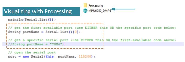
In this code you have to then check the serial port which is defined in it, by default the line that defines if you using Linux or Mac.
Visualizing with Processing
Downloads
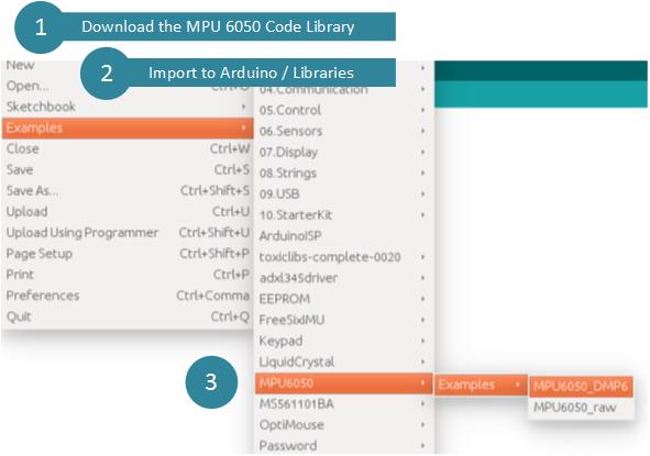
Download MPU6050 Code Libraries | Zip
Download MPU 6050 Datasheet | Pdf


