This is the other model of ESP8266 module, this board has similarity with the ESP8266 V1, ESP8266 7, ESP8266 12E, the difference of this board has an on-board SMD SMC antenna and extra IO port, this module has self-contained SOC with integrated TCP/IP protocol same board what you get from the ESP8266 module. This is capable of hosting an application or access via internet & comes pre-programmed with an AT command set firmware it means you can simply hook this board to your Arduino device get as much WiFi ability.
Compare to ESP8266 12 this module has 6 more pins extra the D0, D1, D2, D3, CLK, CMD, GPIO6-GPIO11 but only the two of them can be used as regular GPIO, we need to modify the board circuitry before we can used this extra IO Pins.
If you want to enable the extra pins the GPIO9 and GPIO10 just follow the diagram below.
Board modification
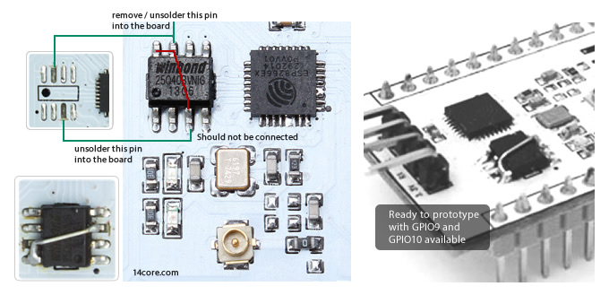
As well as the other ESP module the ESP 201 comes with AT firmware preloaded. Unfortunately we need to modify the board circuitry to make this works bread board friendly. The UART pins should be moved to other side.
Relocating the UART Pins

If you want to use the on-board antenna just follow the instructions below.
Modifying the board antenna

Wiring ESP8266 ESP201 with TTL UART
In this illustration below you need LED and Resistor to test this board via web browser

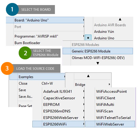
Programming the ESP8266 ESP201 using Arduino IDE
Before you going to flash the ESP8266 ESP201 Board you need to change the IP Address and the password see the illustration below.

If you done uploading you code to the ESP8266 ESP201 Board disconnect GPIO-0 wire and toggle the power of ESP module
you can now remove the USB from the laptop and plug it again.
You can used to Phone to check the if your ESP8266 is up, you can down the app name Fing to check if there is a response from your ESP8266 board. Make it sure that your connected to you home network to execute ping command. The Fing app helps to identify an IP address on ESP8266 module which you can use for driving the GPIO-2 of the ESP8266 board which you connected the LED
Here is the final step you need to used your browser to turn the LED into HIGH.
192.168.XXX.XXX/gpio/0 <- if you use the GIPO 0
192.168.XXX.XXX/gpio/1 <- if you use the GIPO 1
192.168.XXX.XXX/gpio/2 <- if you use the GIPO 2

Download Code Library
Download the Arduino IDE + ESP8266 Code Library |Link
Download Additional Board Manager URLs field Json | Zip
Download ESP8266 Datasheet here | Zip
Download ESP8266 ESP201 PinOut- Diagram | Zip


Pingback:Arduino IDE with ESP8266 Integration for Ease Programming | 14Core.com
Pingback:ESP-201 an ESP8266 breadboard friend
Be aware, that usign the FTDI as power source might work, but it not specced to deliver needed power. So if you have issues flashing or running the ESP use another 3.3V power source.
The ESP8266 chip alone (no memory) might use up to 170mA in Tx mode.
An FTDI chip might use up to 100mA from the USB bus, including the 15mA it needs for its own operation. That leaves 85mA for the ESP8266, which is OK for receive only, or no radio (like flashing). But always move it to another power source for running.
Noted: thanks you.. Have you tried using CP2102 USB-to-Serial?
CP2102 works on my side.