Reading Sensing and Controlling current flow is a requirements in a wide variety of application including, over-current protection circuits, switching mode, battery chargers, power supplies, digital watt meter and programmable current source, etc.. The ACS721 current reading module is based on ACS712 Sensor which can detect AC, DC current signal accurately.
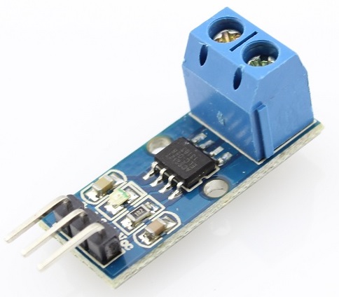
The maximum AC / DC can be detected using ACS712 will reach 30 amp and present current signal can read via analog IO port of Arduino, Product available for this module are 30A, 20A, 5A. for this demonstration we will used the ACS712 30A.


DC Current Measuring Sketch
|
1 2 3 4 5 6 7 8 9 10 11 12 13 14 15 16 17 18 19 |
void setup() { Serial.begin(9600); } void loop() { float average = 0; for(int i = 0; i < 1000; i++) { average = average + (.0264 * analogRead(A0) -13.51) / 1000; //5A mode, if 20A or 30A mode, need to modify this formula to //(.19 * analogRead(A0) -25) for 20A mode and //(.044 * analogRead(A0) -3.78) for 30A mode delay(1); } Serial.println(average); } |
Download the source code here > 14Core DC Current Measure
AC Current Measuring Sketch
|
1 2 3 4 5 6 7 8 9 10 11 12 13 14 15 16 17 18 19 20 21 22 23 24 25 26 27 28 29 30 31 32 33 34 35 36 37 38 39 40 41 42 43 44 45 46 47 48 49 50 51 52 53 54 55 56 |
#define CURRENT_SENSOR A0 // Define Analog input pin that sensor is attached float amplitude_current; // Float amplitude current float effective_value; // Float effective current void setup() { Serial.begin(9600); pins_init(); } void loop() { int sensor_max; sensor_max = getMaxValue(); Serial.print("sensor_max = "); Serial.println(sensor_max); //the VCC on the Arduino interface of the sensor is 5v amplitude_current=(float)(sensor_max-512)/1024*5/185*1000000; // for 5A mode,you need to modify this with 20 A and 30A mode; effective_value=amplitude_current/1.414; //for minimum current=1/1024*5/185*1000000/1.414=18.7(mA) //Only sinusoidal alternating current Serial.println("The amplitude of the current is(in mA)"); Serial.println(amplitude_current,1); //Only one number after the decimal point Serial.println("The effective value of the current is(in mA)"); Serial.println(effective_value,1); } void pins_init() { pinMode(CURRENT_SENSOR, INPUT); } /*Function: Sample for 1000ms and get the maximum value from the S pin*/ int getMaxValue() { int sensorValue; //value read from the sensor int sensorMax = 0; uint32_t start_time = millis(); while((millis()-start_time) < 1000) //sample for 1000ms { sensorValue = analogRead(CURRENT_SENSOR); if (sensorValue > sensorMax) { /*record the maximum sensor value*/ sensorMax = sensorValue; } } return sensorMax; } |
Another Example of the AC712 Alternative Formula
|
1 2 3 4 5 6 7 8 9 10 11 12 13 14 15 16 17 18 19 20 21 22 23 24 25 26 27 28 29 30 31 32 33 34 35 36 37 38 39 40 41 42 43 44 45 46 47 48 49 50 51 52 53 54 55 56 57 58 59 60 61 62 63 |
ACS712 Arduino Code float vcc = 0; void setup() { Serial.begin(9600); } void loop() { vcc = readVcc() / 1000.0; Serial.print(“Vcc: “); Serial.print(vcc); long average = 0; for (int i = 0; i < 100; i++) { average = average + analogRead(A0); delay(1); } average = average / 100; float sensorValue = average * (5.0 / 1023.0); Serial.print(” sense: “); Serial.print(sensorValue, 3); float acoffset = vcc / 2.0; Serial.print(” offst: “); Serial.print(acoffset, 3); float sensitivity = 0.185 * (vcc / 5.0); Serial.print(” sensi: “); Serial.print(sensitivity, 4); float amps = (sensorValue – acoffset) / sensitivity; Serial.print(” Amperes: “); Serial.print (amps); Serial.println(“…”); delay(1000); } long readVcc() { // Read 1.1V reference against AVcc // set the reference to Vcc and the measurement to the internal 1.1V reference #if defined(__AVR_ATmega32U4__) || defined(__AVR_ATmega1280__) || defined(__AVR_ATmega2560__) ADMUX = _BV(REFS0) | _BV(MUX4) | _BV(MUX3) | _BV(MUX2) | _BV(MUX1); #elif defined (__AVR_ATtiny24__) || defined(__AVR_ATtiny44__) || defined(__AVR_ATtiny84__) ADMUX = _BV(MUX5) | _BV(MUX0); #elif defined (__AVR_ATtiny25__) || defined(__AVR_ATtiny45__) || defined(__AVR_ATtiny85__) ADMUX = _BV(MUX3) | _BV(MUX2); #else ADMUX = _BV(REFS0) | _BV(MUX3) | _BV(MUX2) | _BV(MUX1); #endif delay(2); // Wait for Vref to settle ADCSRA |= _BV(ADSC); // Start conversion while (bit_is_set(ADCSRA, ADSC)); // measuring uint8_t low = ADCL; // must read ADCL first – it then locks ADCH uint8_t high = ADCH; // unlocks both long result = (high << 8) | low; result = 1125300L / result; // Calculate Vcc (in mV); 1125300 = 1.1*1023*1000 return result; // Vcc in millivolts } |
Download the source code here > 14Core AC Current Measure
Download AC712 Datasheet here > ACS712-Datasheet


Hey what parameters do I need to change for 30 A sensor
amplitude_current=(float)(sensor_max-512)/1024*5/185*1000000;
1023 – 512 = 511 * 234375 = 119,765,625 quarter microamps / 4,000,000
= 29.9410625 Amps close to 30amp
I see , but can you explain what each number means and reform this amplitude_current=(float)(sensor_max-512)/1024*5/185*1000000; for 30A what do i need to replace
its very unreliable when using arduino with usb, because codes take ideal 5 volts into consideration, while in real world this dosent happen, and thus the readings fluctuate. I have tried and made this work, now all aspects of sensors and formulas are taken from current voltage, which are measured by secret arduino voltmeter.
(512)——-> adc value for 2.5V
1024——->adc value for 5V both are constant for acs712
*5———> 5V arduino analog pin max value
185——->its from datasheet and its for 5A if we will use 30A censor we have to change it 66
amplitude_current=(float)(sensor_max-512)/1024*5/66*1000000 so it will change like this for 30A
And I have a question too How can I use both code for it I mean I have to measure ac and also dc current
Well yet another code for this sensor doesn’t work… literally copied and pasted it, uploaded… my output is as follows:
72.04
72.04
72.04
72.04
72.04
72.04
72.04
72.04
72.03
Thats without pressing the button to connect the motor to the power (which uses around 300mA).
Why on earth does the code from any site never work for this sensor? (I have two of them and both have the same result).
#include
//current censor
const int sensorIn = A1;
int mVperAmp = 66; // use 100 for 20A Module and 66 for 30A Module
int RawValue= 0;
int ACSoffset = 2500;
double Voltage = 0;
double Amps = 0;
void setup() {
}
void loop() {
//Current calculate
RawValue = analogRead(sensorIn);
Voltage = (RawValue / 1024.0) * 5000; // Gets you mV
Amps = ((Voltage – ACSoffset) / mVperAmp);
Serial.print(“Current: ” );
Serial.print( Amps );
Serial.println(” A”);
}
I use this code and it worked on my project bro for 30A censor I hope it will help u too
#include
There is this at the first in code I accidently deleted it
Hi. I connected the acs712 module to Arduino like the figure and tried your code, but it shows the module between negative 28 and 30 amps …… I do not know what to do.
Hi, We are using this sensor for reading ac current but the sensor will read incorrectly and when the sensors are not connected to the arduino mega,there is still a reading output in the lcd.Why is this happening?